http://railroadtraining.biz/arc-tech-net/
Track and Structures Compliance Manual
Volume II Track Safety Standards Chapter 1 Track Safety Standards Subparts A Through F 2026
FRA is issuing this compliance manual pursuant to FRA’s general authority to prescribe regulations and issue orders for every area of railroad safety under 49 U.S.C. §§ 103(g) and 20103(a). This manual does not have the force or effect of law and is not meant to bind the public in any way. FRA will not rely upon this manual as a separate basis for enforcement action or other administrative penalty. Conformity with this manual (as distinct from existing statutes and regulations) is voluntary only, and nonconformity will not affect rights and obligations under existing statutes and regulations.
This document is not intended to, and does not, create any right or benefit, substantive or procedural, enforceable at law or in equity by any party against the United States, its agencies or other entities, officers or employees, or any other person. In addition, this document shall not be construed to create any right to judicial review involving the compliance or noncompliance with this document by the Federal Railroad Administration or the U.S. Department of Transportation, its Operating Administrations or components, its officers or employees, or any other person. Moreover, this document does not provide any basis for a private party to challenge FRA’s exercise of enforcement discretion in a particular case.
Table of Contents
VOLUME II, CHAPTER 1 TRACK SAFETY STANDARDS CLASSES 1 THROUGH 5
Introduction
SUBPART A – GENERAL
§ 213.1 Scope of part
§ 213.3 Application
§ 213.5 Responsibility for compliance
§ 213.7 Designation of qualified persons to supervise certain renewals and inspect track
§ 213.9 Classes of track: operating speed limits
§ 213.11 Restoration or renewal of track under traffic conditions
§ 213.13 Measuring track not under load
§ 213.14 Application of requirements to curved track.
§ 213.15 Penalties
§ 213.17 Waivers
§213.19 Information collection
SUBPART B – ROADBED
§ 213.31 Scope
§ 213.33 Drainage
§ 213.37 Vegetation
SUBPART C – TRACK GEOMETRY
§ 213.51 Scope
§ 213.53 Gage
§ 213.55 Alinement
§ 213.57 Curves; elevation and speed limitations
§ 213.59 Elevation of curved track; (runoff)
§ 213.63 Track Surface
§ 213.65 Combined track alinement and surface deviations
SUBPART D – TRACK STRUCTURE
§ 213.101 Scope
§ 213.103 Ballast; general
§ 213.109 Crossties
§ 213.110 Gage Restraint Measurement Systems
§ 213.113 Defective rails
§ 213.115 Rail end mismatch
§ 213.118 Continuous welded rail (CWR); plan review and approval
§ 213.119 Continuous welded rail (CWR); plan contents
§ 213.121 Rail joints
§ 213.122 Torch cut rail
§ 213.127 Rail fastening systems
§ 213.133 Turnouts and track crossing generally
§ 213.135 Switches
§ 213.137 Frogs
§ 213.139 Spring rail frogs
§ 213.141 Self-guarded frogs
§ 213.143 Frog guard rails and guard faces; gage
SUBPART E – TRACK APPLIANCES AND TRACK – RELATED DEVICES
§ 213.201 Scope
§ 213.205 Derails
SUBPART F – INSPECTION
§ 213.231 Scope
§ 213.233 Track inspections
§ 213.234 Automated Inspection of Track Constructed with concrete Crossties
§ 213.235 Inspection of switches, track crossings, and lift rail assemblies or other transition devices on moveable bridges
(Quiz)on 213.233 & 213.235)
§ 213.237 Inspection of rail
§ 213.239 Special inspections
§ 213.241 Inspection records
APPENDIX
APPENDIX A – SUPERELEVATION IN INCHES/SPEED MPH
APPENDIX B – USE OF PORTABLE TRACK-LOADING FIXTURE (PTLF) IN NON-GRMS TERRITORY
This document was prepared by the Federal Railroad Administation (FRA) Office of Railroad Safety, Track and Structures Division.
Text in italic font in this document is regulatory language, whereas indented paragraphs provide field guidance for FRA inspectors. Indented paragraphs are not to be construed as regulatory language in any manner.
This chapter has been updated since the January 2023 release. Changes include: • Formatting.
• Minor spelling, grammatical, and typographical corrections.
• Extraneous background discussion removed.
• Previous Figure 24 removed; all subsequent figures renumbered.
• Figure 25 revised.
• Defect codes removed.
Track Safety Standards Subparts A Through F
| Introduction |
This chapter provides the necessary information for FRA inspectors to properly apply the Track Safety Standards (TSS) during inspection activities (the term “FRA inspector” also includes State inspectors who are participants in the Federal program). This manual is not to be construed as a modification, alteration, or revision of the published TSS.
In addition to discussing the TSS, this document also discusses certain best practices. This guidance is not legally binding and will not be relied on by the U.S. Department of Transportation (DOT) or FRA as a separate basis for affirmative enforcement action or other administrative penalty. Conformity with such guidance is voluntary, and nonconformity will not affect rights and obligations under existing statutes and regulations.
Any enforcement action instituted against a railroad track owner must be based on the regulations found in 49 CFR Part 213. Inspectors should refer to this document as often as necessary to understand the intent of any particular rule, thereby assuring to the extent practicable the nationally uniform application of these rules as intended by Congress in the Federal Railroad Safety Act of 1970.
Inspectors will not, under any circumstances, adjust, correct, or repair track or appurtenances, nor will they authorize, suggest, or recommend any movements over any track. Full responsibility for these matters rests with the railroad track owner. The inspector will immediately inform the railroad track owner of any track condition not in compliance with the TSS.
The current TSS are contained in the Electronic Code of Federal Regulations (http://www.ecfr.gov).
Inspectors are encouraged to provide suggestions for enhancement of future editions of this document.
This chapter addresses Track Classes 1 through 5. Volume II, Chapter 2 addresses Classes 6 through 9.
Subpart A – General
| § 213.1 Scope of part |
1(a) This part prescribes minimum safety requirements for railroad track that is part of the general railroad system of transportation. In general, the requirements prescribed in this part apply to specific track conditions existing in isolation. Therefore, a combination of track conditions, none of which individually amounts to a deviation from the requirements in this part, may require remedial action to provide for safe operations over that track. This part does not restrict a railroad from adopting and enforcing additional or more stringent requirements not inconsistent with this part.
Guidance: It is important to note that the TSS are minimum safety requirements and are not appropriate for track maintenance purposes.
The VTI Final Rule (78 FR 16100, Mar. 13, 2013) added the phrase “In general” to provide a certain degree of flexibility, to encompass track conditions not necessarily “existing in isolation.” In particular, it refers to ‘‘combined’’ track alinement and surface deviations contained in § 213.65.
While the TSS address specific track conditions that exist in isolation in general, there can sometimes be a combination of track conditions (none of which individually amounts to a deviation of the TSS) that requires remedial action to provide for safe operations over that track. Section § 213.65 specifically addresses a combination of track conditions for curves with operations resulting in more than 5 inches cant deficiency. If an inspector encounters such a condition which is not encompassed in § 213.65, the inspector should also immediately notify the accompanying railroad official of the condition, explain the hazard of such a condition, and encourage prompt remedial action. Where the inspector is not able to convince the railroad to initiate some action, the inspector should refer to the district track specialist for assistance.
1(b) Subparts A through F apply to track Classes 1 through 5. Subpart G and 213.2, 213.3, 213.15, and 213.240 apply to track over which trains are operated at speeds in excess of those permitted over Class 5 track.
Guidance: With the introduction of high-speed passenger train operations, the TSS were revised in 1998 to provide two sets of requirements, one for low-speed track (Classes 1 through 5), and one for high-speed track (Classes 6 through 9). The VTI Final Rule (78 FR 16100, Mar. 13, 2013) further revised Part 213, but mainly Subpart G. The high-speed standards include specific requirements for such operations, which include a number of track-vehicle interaction tests. Section 213.3 (Application), 213.15 (Penalties), and 213,240 (Continuous rail testing) apply to both high and low-speed track.
| § 213.3 Application |
3(a) Except as provided in paragraph (b) of this section, this part applies to all standard gage track in the general railroad system of transportation.
Guidance: Paragraph 3(a) provides that, with certain exceptions listed in paragraph (b) (i.e., plant railroads including “leased track,” certain tourist, scenic, historic, and excursion operations, and certain rapid transit operations), Part 213 applies to all standard gage track in the general railroad system of transportation (general system). The term “general system” “refers to the network of standard gage track over which goods may be transported throughout the nation. . .” 49 CFR Part 209, Appendix A.
3(b) This part does not apply to track:
(1) Located inside an installation that is not part of the general railroad system of transportation (i.e., a plant railroad). As used in this part, a plant railroad means a plant or installation that owns or leases a locomotive, uses that locomotive to switch cars throughout the plant or installation, and is moving goods solely for use in the facility’s own industrial processes. The plant or installation could include track immediately adjacent to the plant or installation if the plant railroad leases the track from the general system railroad and the lease provides for (and actual practice entails) the exclusive use of that track by the plant railroad and the general system railroad for purposes of moving only cars shipped to or from the plant. A plant or installation that operates a locomotive to switch or move cars for other entities, even if solely within the confines of the plant or installation, rather than for its own purposes or industrial processes, will not be considered a plant railroad because the performance of such activity makes the operation part of the general railroad system of transportation. Similarly, this exclusion does not apply to track over which a general system railroad operates, even if that track is located within a plant railroad;
(2) Used exclusively for tourist, scenic, historic, or excursion operations that are not part of the general railroad system of transportation. As used in this part, tourist, scenic, historic, or excursion operations that are not part of the general railroad system of transportation means a tourist, scenic, historic, or excursion operation conducted only on track used exclusively for that purpose (i.e., there is no freight, intercity passenger, or commuter passenger railroad operation on the track); or
(3) Used exclusively for rapid transit operations in an urban area that are not connected to the general railroad system of transportation.
Guidance: Although FRA’s statutory jurisdiction extends to all railroad carriers, FRA has chosen, as a matter of policy, not to impose its regulations on certain categories of rail operations. For example, 213.3(b)(1) generally excludes any railroad whose entire operation is confined to an industrial installation (i.e., a plant railroad), including “leased track” that does not go beyond the plant’s boundaries onto the general railroad system of transportation (general system), from complying with the requirements of Part 213. Likewise, paragraph (b)(2) excludes tourist, scenic, historic, or excursion operations that are not part of the general system while paragraph (b)(3) excludes rapid transit operations in an urban area that are not connected to the general system. As provided in Appendix A to Part 209, the regulations are also not intended to make Part 213 applicable to certain rapid transit systems whose only connection to the general system is a switch permitting receipt of shipments of non-revenue materials from the general system.
FRA’s decision to not exercise its regulatory authority over track used in certain railroad operations in no way constrains the exercise of FRA’s statutory enforcement or emergency order authority under 49 U.S.C. 20104 and 20111. In other words, FRA retains jurisdiction over such track and operations even if it has refrained from exercising its authority in specific instances. For example, FRA retains the authority to issue emergency orders to repair or discontinue use of trackage excluded from the requirements of Part 213 should FRA find that track conditions pose an emergency situation involving a hazard of death, personal injury, or significant harm to the environment. See 49 U.S.C. 20104. If FRA learns that a particular plant railroad not subject to Part 213 is in such disrepair so as to pose a safety hazard of death or injury to a plant railroad employee, a railroad employee, or the public at large, FRA has the option of exercising its authority. FRA may issue an emergency order directing the plant railroad to discontinue using the track until specified repairs are made. If conditions or events in the future tend to demonstrate that track safety within these plants or installations should be more closely regulated, FRA will seek to change the track safety regulations accordingly.
While FRA has chosen not to apply the requirements of Part 213 to trackage used in certain railroad operations, those operations should use the requirements as a guide to ensure that their tracks are capable of carrying rail traffic safely. For example, as a practical application of this policy, FRA expects that the trackage in a plant railroad, at a minimum, meet Class 1 standards. As a general matter, FRA also expects that the requirements of Subparts C and D (geometry and structure) of Part 213 will be met but does not expect a plant railroad to comply with inspection frequency requirements for the intended track class.
On January 24, 2014, FRA published a final rule which, for purposes of clarifying FRA’s longstanding policy statement on its jurisdiction over “plant railroads” added a definition of the term “plant railroad” to Part 213. See 79 FR 4234 (Jan. 24, 2014) (Rail Integrity Final Rule). See also 213.3(b) cited above. That definition specifically stated that the plant railroad exclusion “does not apply to track over which a general system railroad operates, even if that track is located within a plant railroad.” As stated throughout the preamble to that rulemaking document, however, FRA added the definition of “plant railroad” merely as a convenience for readers and intended the definition to be consistent with FRA’s longstanding published policy statement on the extent and exercise of the agency’s jurisdiction. FRA did not intend the Rail Integrity Final Rule to alter the reach of FRA’s traditional exercise of jurisdiction over plant railroads or the applicability of Part 213. As previously stated in Appendix A to Part 209, “The plant railroad itself, however, does not get swept into the general system by virtue of the other railroad’s activity, except to the extent it is liable, as the track owner, for the condition of its track over which the other railroad operates during the incursion into the plant.” Accordingly, while the requirements of FRA’s TSS do not apply to track located within an installation that meets the definition of a “plant railroad,” the track over which a general system railroad operates must comply with the requirements of Part 213 specifically concerning the condition of the track itself. Consequently, track over which a general system railroad operates must comply with Part 213, Subparts B, C, D, and E, which cover minimum requirements for the roadbed, track geometry, track structure, and track appliances. The plant railroad is not required to comply with Part 213, Subpart F, which concerns track inspections and recordkeeping.
Accordingly, the plant railroad may adopt whatever track inspection and recordkeeping procedures it finds appropriate to help maintain the condition of the track over which the general system railroad operates. Similarly, the provisions of Part 213, Subpart A, would apply only to the extent they relate to the condition of the track and the railroad’s associated rights and obligations.
FRA also did not intend for the Rail Integrity Final Rule to alter FRA’s approach to trackage located in an installation that is not part of the general system and that does not own, lease, or use a locomotive to move cars. FRA treats those installations as if they were plant railroads and does not generally apply the requirements of FRA’s TSS to those installations. However, like a plant railroad, and as stated above, the track over which a general system railroad operates must comply with the requirements of Part 213 specifically concerning the condition of the track itself. Moreover, FRA retains its enforcement authority and authority to issue emergency orders to repair or discontinue use of the trackage should FRA find that the track conditions pose an emergency situation involving a hazard of death, personal injury, or significant harm to the environment.
Any questions concerning the applicability of Part 213 must be referred to the district track specialist, who will consult with the Staff Director, Track and Structures Division and the Office of Chief Counsel for guidance concerning the particular entity.
| § 213.4 Excepted track |
A track owner may designate a segment of track as excepted track provided that
4(a) The segment is identified in the timetable, special instructions, general order, or other appropriate records which are available for inspection during regular business hours;
Guidance: The intent of this section is to permit portions of certain low density main tracks and associated yard tracks and sidings to be allowed excepted status and not comply with Subparts B, C, D, and E of the TSS unless otherwise expressly stated. However, by designating a track as excepted, the owner must meet the requirements specified in paragraphs 4(b) through to 4(f).
4(b) The identified segment is not located within 30-feet of an adjacent track which can be subjected to simultaneous use at speeds in excess of 10 miles per hour;
Guidance: This paragraph prohibits excepted track designation of any adjacent track located within a 30-foot envelope of a track that can be subjected to simultaneous use at speeds in excess of 10 mph. As shown in the following figure, the 30-foot dimension is measured between track centerlines and applies to all tracks within that area (e.g., tracks converging at turnouts and rail crossings). In this example, since the far left track operates at greater than 10 m.p.h., only the far right track may be excepted. Simultaneous use means movement of cars or locomotives on both tracks at the same time.
Note: “adjacent track” means any track in proximity to the track in question
39′
26′
10 mph 10 mph
10 mph.
Track greater than 10 mph
13′ 13′
Cannot be
excepted
13′
Cannot be
excepted
May be excepted
Figure 1: Excepted Track within 30-feet of Other Tracks
Operation on any track located within 30 feet of excepted track may be restricted to 10 mph by the physical layout of the tracks, or by definite restrictions placed by the track owner by rule, timetable, special instruction, or other positive instruction or order. These criteria provide the positive protection of trains on higher speed track against a collision with fouling equipment from a potential derailment on the excepted track.
The term “train” is defined in 49 CFR § 236.832 as, “A locomotive or more than one locomotive coupled, with or without cars.” That definition applies to this rule.
A designation of excepted track need only be recorded by the track owner and implemented by issuance of appropriate instructions to all affected employees. The designation need not be filed with FRA. The TSS do not specify which employees the railroad or track owner must notify of excepted track designations; however, in order to ensure maximum safety and compliance with the requirements of this part, FRA recommends that the railroad or track owner notify all employees who are involved with the operation of trains or with engineering functions on excepted track.
4(c) The identified segment is inspected in accordance with 213.233(c) and 213.235 at the frequency specified for Class 1 track;
Guidance: § 213.5(b) provides that a railroad may continue train operations on track segments designated as excepted track without complying with Subparts B, C, D, and E of Part 213. However, a railroad must still comply with the inspection requirements contained in Subpart F for track segments designated as excepted track. Railroads must inspect excepted track in accordance with §§ 213.233(c) and 213.235 at the frequency specified for Class 1 track. Failure to comply will result in a violation and loss of the excepted track privilege until inspection requirements specified in this paragraph are met.
4(d) The identified segment of track is not located on a bridge including the track approaching the bridge for 100 feet on either side, or located on a public street or highway, if railroad cars containing commodities required to be placarded by the Hazardous Materials Regulations (49 CFR Part 172), are moved over the track; and
Guidance: In the application of this paragraph, a public street or highway is defined as a roadway that is open to the public and is owned and maintained by a public entity. This paragraph includes both crossings of public roadways at grade and longitudinal running of the track for extended distances in a public roadway (street trackage).
Under § 214.7, a railroad bridge is defined as follows: 1) a railroad bridge is any structure supporting one or more railroad tracks with a span length of 12 feet or more measured along the track centerline; and 2) the term “bridge” shall apply to the entire structure between the faces of the backwalls of abutments or equivalent components, regardless of the number of spans. The term shall include all structures, whether of timber, stone, concrete, metal, or any combination thereof.
4(e) The railroad conducts operations on the identified segment under the following conditions: (1) No train shall be operated at speeds in excess of 10 miles per hour;
(2) No occupied passenger train shall be operated;
(3) No freight train shall be operated that contains more than five cars required to be placarded by the Hazardous Materials Regulations (49 CFR Part 172); and
(4) The gage on excepted track shall not be more than 4 feet 10¼ inches. (This paragraph (e)(4) is applicable September 21, 1999.)
Guidance: In reference to (e)(1) through (4), a well-documented pattern of repeated or widespread deviations from these requirements by a track owner, including train operations in excess of 10 mph, will effectively terminate the privilege afforded by this section. The affected track would then become subject to all requirements of the TSS.
The word ‘‘occupied’’ in (e)(2) refers to paying and non-paying passengers. It does not include train crew members, track maintenance crews, and other railroad employees who must travel over the track to attend to their work duties.
The gage requirement only applies to the actual measurement itself under load and does not extend to the evaluation of crossties and fasteners that provide the gage restraint. In the case of noncompliance with the gage requirement in excepted track, the railroad may invoke § 213.9(b) as remedial action. [See § 213.9(b) for restrictions.]
4(f) A track owner shall advise the appropriate FRA Regional Office at least 10 days prior to removal of a segment of track from excepted status.
Guidance: The railroad or track owner is required to notify the Track and Structures Division (or Office of Railroad Infrastructure and Mechanical) 10 days before removing trackage from excepted status. A railroad may not move the track from excepted to non-excepted status to operate an occupied passenger train or a train containing more than five cars placarded in accordance with 49 CFR Part 172, unless proper notification procedures are followed.
Inspectors will continue to inspect excepted track and report these inspections on the F6180.96 form. If serious deficiencies are discovered, they will be shown on the inspection form, noting that the track is in excepted status. The railroad or track owner would not be legally obligated by the TSS to correct the deficiencies noted, except for gage deviations in excess of 4 feet 10¼ inches (213 defect code 0053B5). However, if the condition of the track continues to constitute a hazard to life and limb and the track owner fails to alleviate the hazard, the inspector should notify the district track specialist immediately. Issuance of an emergency order would be appropriate to address any serious defects that would pose an immediate safety threat to railroad employees or the public.
This notification provision is intended to prevent the practice FRA has witnessed in the past by some railroads. Specifically, those who remove trackage from excepted status only long enough to move a passenger excursion train or a train with more than five cars containing hazardous materials.
The following examples are provided to inspectors to determine compliance with the provision of excepted track.
Example One: A railroad designates a 2-mile segment of its yard track Number 1, which is Class 1 track, as excepted track. The excepted track segment is located within 25 feet of an adjacent track over which simultaneous operations at speeds up to 20 mph are authorized. Two weeks after the track was designated as excepted track, an inspector discovers five locations in that segment at which Class 1 gage requirements are not being met.
Result: The segment of yard track Number 1 involved is ineligible for designation as excepted track because it violates § 213.4(b) simultaneous use restriction. Therefore, the segment remains subject to provisions of the TSS for Class 1 track. FRA may cite for correction or violation any deviation from the TSS discovered in the segment, such as the five gage defects. The railroad may also be cited, at the FRA inspector’s discretion, for a violation of § 213.4(b) and will include the substantive defects (e.g., gage, alinement, crossties). To remediate this § 213.4(b) defect, a railroad may choose to restrict train operations to 10 mph on all adjacent tracks within 30 feet of the excepted track.
Example Two: A railroad designates yard track number 6, which is classified as Class 1 track, as excepted track at the end of June. The railroad does not conduct any inspections over the track during July.
Result: Yard track number 6 loses its eligibility for designation as excepted track on August 1, and remains ineligible thereafter until the inspections required by § 213.4(c) begins. Starting August 1, the track becomes subject to all provisions of the TSS and remains subject to those requirements until such time as the inspections begin. Violation citations arising from inadvertent violations of the inspection requirement ordinarily should be issued only where safety was impaired or there is evidence of continued noncompliance.
In contrast to violations of the definitional (§ 213.4(a) to (d)) requirements, the unit of violation for noncompliance with the operational limitations is the train. We refer here to occasional and inadvertent noncompliance with operational limitations. A persistent and well-documented pattern of noncompliance with respect to a particular segment may cause the railroad to lose its privilege of designating the segment as excepted track (i.e., the track would no longer qualify for such designation) and compel FRA to use stronger enforcement remedies such as emergency orders. The following examples illustrate this concept.
Example Three: A railroad properly designates a track segment as excepted track and 10 days later it operates a freight train containing 10 placarded tank cars over the track segment.
Result: One violation of § 213.4(e)(3) by the railroad has occurred, not five, because the unit of violation is the train rather than each of the placarded cars exceeding the five-car limit. The segment continues to be excepted track because a violation of an operational limitation does not render the track ineligible for excepted track status.
Example Four: Railroad A properly designates one of its track segments as excepted track. Railroad B’s freight train 2425, using the segment pursuant to a trackage rights agreement with Railroad A, operates over the segment at a speed of 20 mph.
Result: One violation has occurred of § 213.4(e)(2) by Railroad A. The track owner is the responsible party for non-compliant operations over the excepted track. The segment continues to be excepted track.
| § 213.5 Responsibility for compliance |
5(a) Except as provided in paragraph (b) of this section, any owner of track to which this part applies who knows or has notice that the track does not comply with the requirements of this part, shall –
(1) Bring the track into compliance;
(2) Halt operations over that track; or
(3) Operate under authority of a person designated under § 213.7(a), subject to conditions set forth in this part. If the operation is on continuous welded rail (CWR) track, the person under whose authority operations are conducted must also be designated under § 213.7(c).
Guidance: This paragraph describes the action that must be taken by a track owner or railroad once they know or have notice (knowledge standard) that the track is not in compliance with the TSS. The track owner or railroad must:
Bring the track into compliance by either repairing the defects or imposing an appropriate speed restriction.
Remove the track from service, that is, disallowing train operations.
Operate under authority of a qualified person designated under § 213.7(a) in accordance with the following provisions:
§ 213.9 Classes of track: operating speed (Including 9(b), 30-day provision)
§ 213.11 Restoration or renewal of track under traffic conditions.
§ 213.113 Rail defects.
For additional information concerning the required corrective action for defects, see the guidance under § 213.9 (Classes of track; operating speed limit).
5(b) If an owner of track to which this part applies designates a segment of track as “excepted track” under the provisions of § 213.4, operations may continue over that track without complying with the provisions of Subparts B, C, D, and E, unless otherwise expressly stated.
Guidance: The track owner or railroad may designate the track “excepted” provided it meets the requirements of § 213.4.
5(c) If an owner of track to which this part applies assigns responsibility for the track to another person (by lease or otherwise), written notification of the assignment shall be provided to the appropriate FRA Regional Office at least 30 days in advance of the assignment. The notification may be made by any party to that assignment, but shall be in writing and include the following —
(1) The name and address of the track owner;
(2) The name and address of the person to whom responsibility is assigned (assignee); (3) A statement of the exact relationship between the track owner and the assignee; (4) A precise identification of the track;
(5) A statement as to the competence and ability of the assignee to carry out the duties of the track owner under this part; and
(6) A statement signed by the assignee acknowledging the assignment to him of responsibility for purposes of compliance with this part.
Guidance: Paragraph 5(c) requires a track owner to notify FRA’s Track and Structures Division when the responsibility for compliance with this part is assigned to another. Notification must contain the specific information required in this paragraph and shall be made 30 days before the assignment of the responsibility.
5(d) The Administrator may hold the track owner or the assignee or both responsible for compliance with this part and subject to penalties under 213.15.
Guidance: Where the track is not owned by the operating railroad through an arrangement such as a lease agreement, typically the operating railroad (as the assignee) will be cited for violations. However, it may be appropriate to recommend civil penalties against the operating railroad and the owner when both parties contributed to the deficiency. Inspectors must determine the responsible party when recommending civil penalties for noncompliance and alert FRA’s Chief Counsel when violation reports involve parties other than the track owner.
This paragraph also provides that the party responsible for compliance can be other than the actual owner of the track through assignment of responsibility or if the Surface Transportation Board (formerly Interstate Commerce Commission) has issued a directed service order. FRA may hold responsible any party contracted by the track owner to ensure compliance with this part. FRA may hold the track owner, the assignee, or both responsible.
5(e) A common carrier by railroad which is directed by the Surface Transportation Board to provide service over the track of another railroad under 49 U.S.C. 11123 is considered the owner of that track for the purposes of the application of this part during the period the directed service order remains in effect.
Guidance: On rare occasions, such as a cessation of service by a railroad, the Surface Transportation Board directs a railroad, other than the track owner, to provide service, the designated operator shall be considered as the owner for the purposes of compliance with the TSS.
5(f) When any person, including a contractor for a railroad or track owner, performs any function required by this part, that person is required to perform that function in accordance with this part.
Guidance: Both employees of railroads and track owners, and contractors to railroads, are subject to the requirements of the TSS when they perform functions required by the TSS.
| § 213.7 Designation of qualified persons to supervise certain renewals and inspect track |
7(a) Each track owner to which this part applies shall designate qualified persons to supervise restorations and renewals of track under traffic conditions. Each person designated shall have—
(1) At least —
(i) 1 year of experience in railroad track maintenance under traffic conditions; or
(ii) A combination of experience in track maintenance and training from a course in track maintenance or from a college level educational program related to track maintenance.
(2) Demonstrated to the owner that he or she—
(i) Knows and understands the requirements of this part that apply to the restoration and renewal of the track for which he or she is responsible;
(ii) Can detect deviations from those requirements; and
(iii) Can prescribe appropriate remedial action to correct or safely compensate for those deviations; and
(3) Authorization from the track owner to prescribe remedial actions to correct or safely compensate for deviations from the requirements of this part.
7(b) Each track owner to which this part applies shall designate qualified persons to inspect track for defects. Each person designated shall have—
(1) At least—
(i) 1 year of experience in railroad track inspection; or
(ii) A combination of experience in track inspection and training from a course in track inspection or from a college level educational program related to track inspection;
(2) Demonstrated to the owner that he or she—
(i) Knows and understands the requirements of this part that apply to the inspection of the track for which he or she is responsible;
(ii) Can detect deviations from those requirements; and
(iii) Can prescribe appropriate remedial action to correct or safely compensate for those deviations; and
(3) Authorization from the track owner to prescribe remedial actions to correct or safely compensate for deviations from the requirements of this part, pending review by a qualified person designated under paragraph (a) of this section.
Guidance: Inspectors may request verification of the experience and qualifications of the supervisory and track inspection personnel from a track owner. The submission of a seniority roster or job awarding bulletin is not to be considered as satisfactory identification of qualified employees or as a basis for their designation. The owner should make specific names of individuals and their qualifications available in writing. If the inspector is in doubt as to the qualifications of the owner’s supervisory or inspection personnel, the inspector should examine the owner’s inspection records. The TSS require the retention of track inspection reports for 1 year. Should the records consistently fail to reflect the actual track conditions, questions can be raised as to the competence and/or qualifications of the persons included in the list.
Paragraphs (a)(2)(i) and (b)(2)(i) clarify that the requirements for a person to be qualified under this section concern the portions of Part 213 necessary for the person to perform his/her duties. The person is not required to know or understand specific requirements of this part not necessary to fulfill his or her duties. For example, track foremen and inspectors may not be required to know or understand vehicle qualification and testing requirements for high cant deficiency operations in track Classes 1 to 5 in fulfilling their duties.
When in doubt as to the qualifications of an owner’s supervisors or inspectors, the inspector should discuss the matter with the railroad.
7(c) Individuals designated under paragraphs (a) or (b) of this section that inspect continuous welded rail (CWR) track or supervise the installation, adjustment, and maintenance of CWR track in accordance with the written procedures of the track owner shall have:
(1) Current qualifications under either paragraph (a) or (b) of this section;
(2) Successfully completed a comprehensive training course specifically developed for the application of written CWR procedures issued by the track owner;
(3) Demonstrated to the track owner that the individual:
(i) Knows and understands the requirements of those written CWR procedures; (ii) Can detect deviations from those requirements; and
(iii) Can prescribe appropriate remedial action to correct or safely compensate for those deviations; and
(4) Authorization from the track owner to prescribe remedial actions to correct or safely compensate from deviation from the requirements in these procedures and successfully completed a recorded examination on those procedures as part of the qualification process.
Guidance: As CWR track has characteristics inherently different than those of traditional jointed rail, track owners are required to designate which individuals are specifically qualified to inspect or supervise the installation, adjustment, and maintenance of CWR. In addition to the qualifications that an individual must have under either paragraph (a) or (b), an individual designated under paragraph (c) must have completed a CWR training course and be well-versed in the maintenance of CWR track as detailed in the track owner’s CWR plan. The comprehensive nature of the training course is more important than its duration; therefore, the employee must successfully complete an in-depth initial training course of the track owner’s written CWR procedures and continue subsequent periodic re-training thereafter, pursuant to the training program required by § 213.119(i). In addition, all individuals qualified on CWR for train operations must successfully complete a recorded examination on the track owner’s CWR procedures. This recorded examination may be, for example, a traditional written examination, an electronic file of a computerized interactive training course that concludes with an examination, or a record of a supervisor’s oral testing of the employee’s knowledge through practical field application. Due to the language of the regulation, track owners have flexibility to test an individual’s knowledge to one of the previously stated methods. However, it should be noted that the results of the examination must be recorded so that FRA may inspect the basis for the qualification of an individual under paragraph (c).
7(d) Persons not fully qualified to supervise certain renewals and inspect track as required in paragraphs (a) through (c) of this section, but with at least one year of maintenance-of-way or signal experience, may pass trains over broken rails and pull aparts provided that—
(1) The track owner determines the person to be qualified and, as part of doing so, trains, examines, and re-examines the person periodically within two years after each prior examination on the following topics as they relate to the safe passage of trains over broken rails or pull aparts: rail defect identification, crosstie condition, track surface and alinement, gage restraint, rail end mismatch, joint bars, and maximum distance between rail ends over which trains may be allowed to pass. The sole purpose of the examination is to ascertain the person’s ability to effectively apply these requirements and the examination may not be used to disqualify the person from other duties. A minimum of four hours training is required for initial training;
(2) The person deems it safe and train speeds are limited to a maximum of 10 m.p.h. over the broken rail or pull apart;
(3) The person shall watch all movements over the broken rail or pull apart and be prepared to stop the train if necessary; and
(4) Person(s) fully qualified under § 213.7 are notified and dispatched to the location promptly for the purpose of authorizing movements and effecting temporary or permanent repairs.
Guidance: Paragraph (d) allows employees to be qualified for the specific purpose of authorizing train movements over broken rails or pull-aparts. This section requires the employees to have at least 1 year of maintenance-of-way or signal experience and a minimum of 4 hours of training, plus an examination (and periodic re-examination within 2 years of each examination) on requirements related to the safe passage of trains over broken rails and pull-aparts. The purpose of the examination is to ascertain the person’s ability to effectively apply these requirements. A railroad may use the examination to determine whether a person should be allowed to authorize train movements over broken rails or pull-aparts.
The maximum speed over broken rails and pull-aparts shall not exceed 10 mph. However, movement authorized by a person qualified under this subsection may further restrict speed, if warranted by the particular circumstances. The person qualified under this paragraph must be present at the site and able to instantly communicate with the train crew so that the movement can be stopped immediately, if necessary.
Fully qualified persons under § 213.7 must be notified and dispatched to the location promptly to assume responsibility for authorizing train movements and effecting repairs. The word “promptly” is meant to provide the railroad with flexibility to pass trains over the condition prior to the time the fully qualified person would report to the scene. Railroads may permit persons qualified under § 213.7(d) to authorize multiple train movements over such conditions, but the person qualified under § 213.7(d) must examine the broken rail or pull-apart area initially, and before each subsequent movement, to ensure the location is safe for the passage of the next train.
7(e) With respect to designations under paragraph (a) through (d) of this section, each track owner shall maintain records of—
(1) Each designation in effect;
(2) The date each designation was made; and
(3) The basis for each designation, including the method used to determine that the designated person is qualified.
Guidance: Failure of the owner to have and maintain records designating employees and the basis for each designation is a deviation from the TSS. Incomplete qualification records would also constitute a deviation from the standards. Designated employees include supervisors, inspectors, and those partially qualified to pass trains over broken rails and pull-aparts. Inspectors are also instructed to note that incomplete qualification records may not reflect the actual qualification of an individual. As such, a record deficiency shall not be the sole basis for a defect or civil penalty recommendation for not having a qualified designated person performing these functions. If there are questions about the qualifications of an individual, it will be necessary for the inspector to interview railroad or contractor employees.
7(f) Each track owner shall keep designation records required under paragraph (e) of this section readily available for inspection or copying by the Federal Railroad Administration during regular business hours, following reasonable notice.
| § 213.9 Classes of track: operating speed limits |
9(a) Except as provided in paragraph (b) of this section and §§ 213.57(b), 213.59(a), 213.113(a), and 213.137(b) and (c), the following maximum allowable operating speeds apply
| Over track that meets all of the requirements prescribed in this part for —- | The maximum allowable speed for freight trains is —- | The maximum allowable speed for passenger trains is —– |
| Excepted | 10 | N/A |
| Class 1 track | 10 | 15 |
| Class 2 track | 25 | 30 |
| Class 3 track | 40 | 60 |
| Class 4 track | 60 | 80 |
| Class 5 track | 80 | 90 |
[In miles per hour]
Guidance: The TSS classify track solely on the basis of authorized speeds for freight and passenger trains. Tolerances are specified in the TSS for each class of track. A deviation beyond the limiting tolerances for Classes 1 through 5 requires repair, or reduction of speeds to the appropriate class. The only structural or geometry defect that is applicable on excepted track is gage exceeding 4 feet 10¼ inches.
The initial speed of any track is based on the design characteristics of the track. FRA does not set the speed, and railroads are required to keep track in compliance with the requirements of Part 213 for the class of track they choose to operate. In addition to track design characteristics, speeds may be set by other factors such as the type of signal apparatus. Maximum speeds are also limited if a signal system is not in place on a track (refer to 49 CFR Part 236 for further information).
As described in paragraph (a), the maximum allowable operating speed for each class of track is shown in the table. However, the maximum allowable operating speed on a curve is also limited by the geometry parameters contained in § 213.57(b) [Unbalance] and § 213.59(a) [Superelevation]. Additionally, §§ 213.113 and 213.137(b) and (c) prescribe specific speeds that may not be exceeded when certain conditions exist in the track. The maximum speed at a given location is determined by the most restrictive speed allowable under §§ 213.9(a), 213.57(b), 213.59(a), 213.113, and 213,137.
For example, a speed for a passenger train based on the elevation of a given curve may be only 18 mph, even though the track may otherwise comply with a higher track class.
Some defects are not directly associated with a particular track classification, such as those under § 213.103 Ballast. These defects are referred to as non-class specific defects by the FRA. When a railroad inspector discovers a non-class-specific defect (as with all defects) the railroad inspector must initiate immediate action per § 213.233(d). The remedial action taken by the railroad inspector must be recorded per § 213.241(b). For non-class specific defects, the record must show a reasonable explanation of the action taken. For example, “repaired before next train” would be appropriate for serious conditions. On the other hand, a notation for a defect such as vegetation that indicates it is scheduled for cutting by a weed mower by a specific date within 30-days may be appropriate.
A non-class specific defect may not pose an immediate hazard for one train movement, but the condition may deteriorate to become a hazard to following trains. It is reasonable to expect that conditions such as loose or missing frog bolts or braces be repaired as quickly as possible. However, a qualified railroad representative under § 213.7 may determine that the condition is not an immediate hazard and decide to call for assistance to make the repairs, or the representative may decide to end the inspection, retrieve the necessary repair materials, and return later to make the repairs. In some cases, the representative may determine that a speed restriction is appropriate.
When non-class-specific defects are scheduled for repair, railroad inspectors shall continue to report the defect on their inspection reports until it is corrected. However, the 30-day limit for any given defective condition cannot be exceeded.
Non-class specific defects allow a railroad or track owner flexibility in resolving the defective conditions while continuing rail service over the track. One loose frog bolt, out of several, would seldom constitute an immediate hazard, provided that the frog was otherwise secure. On the other hand, a missing cotter pin in a critical location, such as in a connecting rod bolt, could have serious consequences.
One or two loose braces are usually not considered to be an immediate hazard, provided that the other braces are in an acceptable functional condition to support the stock rail. On the other hand, several consecutively loose braces, especially in the higher track classes, could be more serious.
Intermittent patches of vegetation that interfere with the trackside duties of train crews may not be an immediate hazard, but vegetation brushing the sides of rolling stock may have the potential of contributing to the injury of an employee who is riding on the side of a car.
As the above examples illustrate, non-class-specific defects (those defects not associated with a particular track classification) must be considered in the context of the specific circumstances involved. The existence of a non-class specific defect under one set of circumstances may not be serious, while the identical condition under other circumstances may constitute a serious safety concern. Although some non-class specific defects may not present an immediate hazard, these conditions will only degrade under train traffic. Therefore, both railroad and FRA inspectors need to record these defects for remedial or corrective action.
FRA inspectors should approach non-class specific defects identified during inspections following the guidance below:
• Record all non-complying conditions, including non-class-specific defects such as a single loose or missing frog bolt or switch brace. Care must be taken to conduct a thorough inspection, recording the location, type, and size of each defect discovered.
• Evaluate the remedial action taken by the carrier. If an inspector becomes aware that the remedial action, or lack thereof, for a non-class-specific defect is not sufficient based on the circumstances, the inspector should seek a more appropriate action from the carrier. For a non-class-specific defect that is an imminent hazard, such as a missing nut on a connecting rod bolt, the inspector should immediately inquire as to the remedial action planned by the carrier.
• If the railroad does not initiate appropriate remedial action, the inspector should consider recommending a violation. If the railroad has been advised that a violation has been recommended and has not initiated appropriate remedial action, the inspector should be prepared to issue a Special Notice for Repairs, under the guidelines described in Chapter 4 of this manual, and in consultation with the district track specialist.
• In the case of a non-class-specific defect that did not pose an immediate hazard when the defect was recorded and the inspector discovers that no action was taken within a reasonable time frame after the carrier had knowledge of the defect, the inspector should consider the enforcement options described in item 3 above. In any case, if no appropriate action was taken within 30 days, the inspector should recommend a violation following the guidance in Volume 1, Chapter 4 of this manual.
When a railroad representative places a slow order on a segment of track for a defect for immediate remedial action, any other items within the same slow order segment may potentially also be considered “protected,” but may still be defects if found in the same inspection and were present prior to the slow order. For example, an FRA inspector finds a defect at Milepost (MP) 5.5 and the railroad immediately places a slow order from MP 5.0 to MP 6.0. During the same inspection, the FRA inspector also finds a condition at MP 5.8 that would be a defect without the speed restriction. While the defect at MP 5.8 is protected under the slow order just imposed, it was obviously a defect prior to the placement of the temporary slow order. The FRA inspector can record a defect at MP 5.8.
9(b) If a segment of track does not meet all of the requirements of its intended class, it is reclassified to the next lowest class of track for which it does meet all of the requirements of this part. However, if the segment of track does not at least meet the requirements of Class 1 track, operations may continue at Class 1 speeds for a period of not more than 30 days without bringing the track into compliance, under the authority of a person designated under § 213.7(a), after that person determines that operations may safely continue and subject to any limiting conditions specified by such person.
Guidance: A track segment must meet all the requirements for its designated class. Where a track segment does not meet all the requirements, railroads can reclassify the segment for the next lowest class for which it complies. For example, on Class 3 Track, where the alinement mid-chord offset from a 62-foot chord on a tangent track measured 2-inches, the railroad can elect to reduce the speed equivalent to Class 2 track. This is usually accomplished by issuing a temporary speed restriction over the location until the defect is repaired.
If a deviation exceeds Class 1 standards, operations may continue for not more than 30 days over the deviation, not exceeding Class 1 speeds. This is only permitted after a person designated and qualified under § 213.7(a) determines that operations may safely continue and specifies limiting conditions, if any. The designated person must have personally seen and evaluated the deviation.
The 30-day limit for any given condition cannot be exceeded. The 30-day period commences when:
• An FRA inspector notifies the carrier or issues notice with a Form F6180.96.
• A person designated under § 213.7 records the defect on a track owner’s record of inspection.
• Notice of a substandard condition is received from a third party.
• The track owner is deemed to have constructive knowledge if the defect was discoverable through properly performed track inspections required by the TSS, even if the defect was not reported on the owner’s record of inspection.
Several other points concerning § 213.9(b) should be noted:
• Regarding constructive knowledge referenced above, FRA inspectors should not attempt to predict an exact date on which a sub-Class 1 defect first existed. In most cases, a reasoned approximation (with accompanying explanation of the basis for the inspector’s conclusions) will be sufficient to show that § 213.9(b) is not available to the track owner. Because of the serious implications presented by the application of the constructive knowledge test, inspectors should use this authority judiciously.
• When a determination has been made that operations may safely continue over a segment, the 30-day period applies to all sub-Class 1 defects present in the segment at that time. The 30-day period is an appropriate remedial action for sub-Class 1 defects and the 30-day period can only be applied one time. At the expiration of the 30-day period, the defects must be repaired, the track placed into excepted track status (if permissible), or the track must be removed from service.
• The limiting conditions, if any, placed on operations must be in a form generally used by the track owner to communicate operating restrictions to its personnel and to any other railroads authorized to use the track involved. If a train operating over the track fails to comply with any such condition, one violation of § 213.9(b) by the track owner has occurred, regardless of the identity of the operator of the train.
• As noted in § 213.9(a), § 213.113 exclusively governs further operations over defective rails listed in § 213.113(c). Therefore, remedial action under § 213.9(b) may not be used for those defects.
The following table shows examples of those sections in the TSS that are “class-specific,” “speed defined,” and “non-class-specific.” This table is not all-inclusive and is only a reference instrument. Inspectors should refer to the specific guidance under each section for further details and instructions on each item listed in the table. For the purposes of this table:
Class-specific means those defects that are not permissible in a specific class or classes of track and may be remediated by lowering the class of track, or, if the segment of track does not at least meet the requirements of Class 1 track, operations may continue at Class 1 speeds under § 213.9(b) for not more than 30 days.
Speed-defined means those conditions which are permissible at a specific or calculated speed.
Non-class-specific means those defects as outlined in the guidance for § 213.9 which are not associated with a specific track class.
| Section | Topic | Class specific | Speed defined | Non-class specific [1] |
| 213.33 | Drainage | X | ||
| 213.37 | Vegetation | X | ||
| 213.53(b) | Gage | X | ||
| 213.55 | Alinement | X | ||
| 213.57(a) | Maximum elevation in curves | X | ||
| 213.57(b) | Curves; elevation and speed limitations (V-Max) | X | ||
| 213.103 | Ballast; general | X | ||
| 213.109(b)(2) | Crossties not effectively distributed | X | ||
| 213.109(b)(3) | Joint tie defects | X | ||
| 213.109(b)(4) | Minimum number of ties in a 39-ft track segment | X | ||
| 213.110 | Gage Restraint Measurement Systems | X | ||
| 213.113 | Defective rails | X | ||
| 213.115 | Rail end mismatch | X | ||
| 213.119 | Continuous welded rail; general | X | ||
| 213.121(a) | Each rail joint, insulated joint, and compromise joint shall be of a structurally sound design and dimensions for the rail on which it is applied | X | ||
| 213.121(b) | Classes 3 through 5: joint bar cracked, broken, or because of wear allows excessive vertical movement of either rail when bolts are tight | X | ||
| 213.121(c) | If a joint bar is cracked or broken between the middle two bolt holes it shall be replaced | X [3] | ||
| 213.121(d) | In the case of conventional jointed track, each rail shall be bolted with at least two bolts … in classes 2 through 5 and with at least one bolt on Class 1 track | X | ||
| 213.121(e) | In the case of continuous welded rail track, each rail shall be bolted with at least two bolts at each joint | X [3] | ||
| 213.123 | Tie plates | X |
| Section | Topic | Class specific | Speed defined | Non-class specific [1] |
| 213.121(f) | Each joint bar shall be held in position by track bolts tightened to allow the joint bar to firmly support the abutting rail ends…. | X | ||
| 213.127 | Rail fastenings | X | ||
| 213.133(a) | Turnouts and track crossings generally | X | ||
| 213.133(b) | Classes 3 through 5 … shall be equipped with anchors on each side of track crossings and turnouts…. | X | ||
| 213.133(c) | Each flangeway at turnouts and track crossings shall be at least 1½ inches wide | X [3] | ||
| 213.135(a) | Each stock rail must be securely seated in switch plates…. | X | ||
| 213.135(b) | Each switch point shall fit its stock rail; excessive lateral or vertical movement | X | ||
| 213.135(b) | Broken or cracked switch point rails … where remedial actions C, D, or E require the use of joint bars…. | X | ||
| 213.135(c) | Each switch shall be maintained so that the outer edge of the wheel tread cannot contact the gage side of the stock rail. | X [2] | ||
| 213.135(d) | The heel of each switch rail shall be secure…. | X | ||
| 213.135(e) | Each switch stand and connecting rod shall be securely fastened…. | X | ||
| 213.135(f) | Each throw lever shall be maintained so that it cannot be operated with the lock or keeper in place. | X [2] | ||
| 213.135(g) | Switch position indicator | X | ||
| 213.135(h) | Unusually worn or chipped switch points…. | X [2] | ||
| 213.137(a) | Flangeway depth | X | ||
| 213.137(b) | If a frog point is chipped, broken, or worn more than ⅝ inch down and 6 inches back, operating speed over that frog may not be more than 10 mph | X |
| Section | Topic | Class specific | Speed defined | Non-class specific [1] |
| 213.137(c) | If the tread portion of a frog casting is worn down more than ⅜ inch below the original contour, operating speed over that frog may not be more than 10 mph | X | ||
| 213.139(a) | The outer edge of a wheel shall not contact the gage side of a spring wing rail. | X [2] | ||
| 213.139(b) | The toe of each wing rail shall be solidly tamped…. | X | ||
| 213.139(c) | Each frog with a bolt hole defect or head-web separation shall be replaced. | X [3] | ||
| 213.139(d) | Each spring shall have compression…. | X | ||
| 213.139(e) | The clearance between the hold-down housing and horn…. | X | ||
| 213.141(a) | The raised guard on a self-guarded frog shall not be more than three eighths of an inch. | X [3] | ||
| 213.205 | Derails | X | ||
| [1] Non-class-specific defects found during an inspection by a qualified railroad inspector and not immediately repaired must be noted on the track inspection form. If not immediately repaired, remedial action shall be taken by an individual qualified under § 213.7 (a). The 30-day period represents the maximum duration that FRA permits any non-class-specific defect(s) to remain in the track. Furthermore, it is not intended to create a 30-day allowance for all types of defects as immediate repair or a more restrictive remedial action may be appropriate at the time of the railroad track owner knows or has notice of the defect(s).. [2] While Part 213 does not require the railroad to take the track out of service, due to the severity of these defects, FRA recommends that railroads take the track out of service. At a minimum, however, the railroad should invoke remedial action § 213.9(b). [3] This class-specific defect requires remedial action § 213.9(b). | ||||
Table 1: Class-Specific, Non-Class-Specific, and Speed-Defined Defects
| § 213.11 Restoration or renewal of track under traffic conditions |
If during a period of restoration or renewal, track is under traffic conditions and does not meet all of the requirements prescribed in this part, the work on the track shall be under the continuous supervision of a person designated under § 213.7(a) and, as applicable, § 213.7(c). The work on the track shall also be subject to any limiting conditions specified by such person. The operating speed cannot be more than the maximum allowable speed under § 213.9 for the class of track concerned. The term ‘‘continuous supervision’’ as used in this section means the physical presence of that person at the job site. However, since the work may be performed over a large area, it is not necessary that each phase of the work be done under the visual supervision of that person.
Guidance: This section specifies that a person designated under § 213.7(a) must provide continuous supervision during work periods when maintenance is performed on track that is under traffic conditions and does not meet the requirements of Part 213. The section is
specific in that each phase of the restoration or renewal need not be under the visual supervision of that person, but the person must be present at the job site in direct control of the work and have direct knowledge of the condition of the track over which they permit a train or trains to pass.
Continuous supervision may be met if the work is broken into several segments over a large area. Inspectors must use judgment and experience in applying this limitation to the general rule. The essential questions are whether the specific circumstances of a given project permit effective supervision by the designated person, and whether such supervision is being properly exercised. An example of an acceptable application of this paragraph would be a large tie and surfacing unit that has cleared a track for a short period to allow the passage of a train based on the qualified person determining that the track is safe for operation. On the other hand, if a switch gang is working separately from the tie and surfacing crew in the same general vicinity, a qualified person must be with that work unit.
The qualified person at a worksite is responsible for ensuring that trains passing through the work area do so at a speed not more than the maximum allowable for the class of track concerned. For example, if during a crosstie and resurfacing project on tangent track, the crosslevel at a location measures 2-1/2”, the designated person must limit the speed of trains over the location to no more than the maximum allowable for Class 1 track (10 mph for freight trains and 15 mph for passenger trains). Similarly, a welder working on a frog with more than 3/8” of the tread portion worn down or removed must limit speeds over the location to 10 mph until the tread portion is appropriately built up and the frog complies with the requirements of § 213.137(c) and (d).
At the end of a work period, when the designated person leaves the worksite, the track must comply with the TSS. If at such time the repair is not yet complete, it is acceptable for the designated person to determine that the track is safe for operation at Class 1 speeds and utilize § 213.9(b) as a remedial action. As outlined in § 213.9(b), the 30-day limit for any given condition may not be exceeded. This provision does not extend that limit for any
previously-identified condition for which a § 213.9(b) remedial action was already initiated.
| § 213.13 Measuring track not under load |
When unloaded track is measured to determine compliance with requirements of this part, the amount of rail movement, if any, that occurs while the track is loaded must be added to the measurements of the unloaded track.
Guidance: In addition to the static (unloaded) geometry measurements taken, the amount of visually detectable dynamic (loaded) deflection that occurs under train movement must be considered. This includes the amount of vertical or lateral rail deflection occurring between a rail base and a tie plate or a tie plate and a crosstie; from voids between the crosstie and ballast section resulting from elastic compression; or any combination of the above. Each deflection under the running rails must be measured and properly considered when computing the collective deviations under load. It is very important that consideration be given to both rails when measuring these deflections.
Static gage 57″
Dynamic movement 1/2″ Dynamic gage = 57-1/2″
Figure 2: Measuring Track Not Under Load
Vertical and lateral deflections may be found at locations such as rail joints and turnout locations with poor wooden crossties and conventional cut-spike fastening conditions or at bridge abutments and over culverts where the subgrade has settled.
| § 213.14 Application of requirements to curved track. |
Unless otherwise provided in this part, requirements specified for curved track apply only to track having a curvature greater than 0.25 degree.
Guidance: The section defines what is meant by curved track for the purpose of application of requirements for curved track. Unless otherwise provided in this part, requirements specified for curved track apply only to track having a curvature greater than 0.25 degree. This definition is intended to apply in all sections where limits for curved track are specified, unless otherwise provided.
Please note that, by implication of this section, track measurement systems required for compliance with Part 213 must be able to detect curves with this minimum specified degree of curvature.
| § 213.15 Penalties |
15(a) Any person who violates any requirement of this part or causes the violation of any such requirement is subject to a civil penalty of at least $908 and not more than $29,707 per violation, except that: Penalties may be assessed against individuals only for willful violations, and, where a grossly negligent violation or a pattern of repeated violations has created an imminent hazard of death or injury to persons, or has caused death or injury, a penalty not to exceed $118,826 per violation may be assessed. “Person” means an entity of any type covered under 1 U.S.C. 1, including but not limited to the following: a railroad; a manager, supervisor, official, or other employee or agent of a railroad; any owner, manufacturer, lessor, or lessee of railroad equipment, track, or facilities; any independent contractor providing goods or services to a railroad; any employee of such owner, manufacturer, lessor, lessee, or independent contractor; and anyone held by the Federal Railroad Administrator to be responsible under § 213.5(d) or § 213.303(c). Each day a violation continues shall constitute a separate offense. See FRA’s website at www.fra.dot.gov for a statement of agency civil penalty policy.
15(b) Any person who knowingly and willfully falsifies a record or report required by this Part may be subject to criminal penalties under 49 U.S.C. 21311.
Guidance: This section covers all subparts of Part 213, including a schedule of civil penalties found on FRA’s website: https://railroads.dot.gov/legislation-regulations/civil penalties-schedules-guidelines.
| § 213.17 Waivers |
17(a) Any owner of track to which this part applies, or other person subject to this part, may petition the Federal Railroad Administrator for a waiver from any or all requirements prescribed in this part. The filing of such a petition does not affect that person’s responsibility for compliance with that requirement while the petition is being considered.
Guidance: Inspectors have no authority under the TSS to grant waivers.
17(b) Each petition for a waiver under this section must be filed in the manner and contain the information required by Part 211 of this chapter.
Guidance: Per 49 CFR 211.7(b) and 211.45(f), any petition for waiver must be filed by the owner or designated operator with the Docket Clerk, Office of Chief Counsel, in Washington, D.C. In addition to this chapter, inspectors should also reference the FRA Office of Railroad Safety’s General Manual, Chapter 5 Complaint and Waiver Investigations, for guidance and information regarding waiver procedures.
General Manual, Chapter 5 indicates that waiver petitions may also be addressed to an FRA manager or specialist. In the past, most petitions have been addressed to the chairperson of the FRA Railroad Safety Board as most waivers are decided by the Board.
17(c) If the Administrator finds that a waiver is in the public interest and is consistent with railroad safety, the Administrator may grant the exemption subject to any conditions the Administrator deems necessary. Where a waiver is granted, the Administrator publishes a notice containing the reasons for granting the waiver.
Guidance: Typically, waivers bear the signature of AA/Chief Safety Officer, or his/her delegate. Inspectors should keep updated with any waivers in effect in their assigned territory which are relevant to their job activities.
| § 213.19 Information collection |
19(a) The information collection requirements of this part were reviewed by the Office of Management and Budget pursuant to the Paperwork Reduction Act of 1995 (44 U.S.C. 3501 et seq.) and are assigned OMB control number 2130-0010.
19(b) The information collection requirements are found in the following sections: §§ 213.4, 213.5, 213.7, 213.17, 213.57, 213.119, 213.122, 213.233, 213.237, 213.241, 213.303, 213.305, 213.317,213.329, 213.333, 213.339, 213.341, 213.343, 213.345, 213.353, 213.361, 213.369.
Subpart B – Roadbed
| § 213.31 Scope |
This subpart prescribes minimum requirements for roadbed and areas immediately adjacent to roadbed.
| § 213.33 Drainage |
Each drainage or other water carrying facility under or immediately adjacent to the roadbed must be maintained and kept free of obstruction, to accommodate expected water flow for the area concerned.
Guidance: One of the most essential elements of track maintenance is a comprehensive drainage system. Drainage facilities (bridges, trestles, or culverts) should be given careful detailed consideration during inspections. Openings under the track are used to channel and divert water from one side of the roadbed to the other.
The rule specifies that each drainage structure shall be maintained and the inspector should note conditions that would affect the integrity of the structure, such as culvert pull-aparts or separations, crushing or uneven settlement due to failure of or lack of head walls (in conjunction with frost action), too steep a gradient, and insufficient support.
Drainage openings must also be inspected and notice given where debris has accumulated to such an extent that expected water flow cannot be accommodated.
Most railroad drainage structures have existed for many years and, if properly maintained and kept free of debris, they are considered adequately designed to accommodate expected water flow, even though recent high-water marks may be slightly above the inlet opening.
Culverts designed with submerged inlets are common. Where questions are raised concerning the adequacy of drainage structures, the district track specialist should be consulted.
Inspectors must take note of the conditions of:
• Right-of-way ditches.
• Culverts, trestles, and bridge inlets.
• Water carrying structures or passageways.
• Outlets or tail ditches.
• Berm ditches.
• Scouring of embankments, piling or piers in channels or at abutments. • Filling in of passageways from silting, sand wash, or debris.
Inspectors must notify the track owner of any drainage condition deemed hazardous, or potentially hazardous, to the safety of train operations over the track.
| § 213.37 Vegetation |
Vegetation on railroad property which is on or immediately adjacent to roadbed shall be controlled so that it does not —
37(a) Become a fire hazard to track-carrying structures;
Guidance: Inspectors must be aware that live and dead growth, drift, tumbleweeds, debris, etc., can constitute fire hazards to timber bridges, trestles, wooden box culverts, and other track carrying structures.
37(b) Obstruct visibility of railroad signs and signals;
(1) along the right-of-way, and
(2) at highway-rail crossings; (This paragraph (b)(2) is applicable September 21, 1999.)
Guidance: This paragraph includes a requirement to clear vegetation from signs and signals along railroad rights-of-way and at highway-rail grade crossings. Because the scope of Part 213 limits vegetation requirements to railroad property, this is not intended to be an attempt to dictate standards for surrounding landowners. This paragraph also requires signs and signals on railroad property at highway-rail grade crossings be kept clear of vegetation and is intended to provide adequate visibility of these devices for the traveling public. It is not intended to preempt State or local requirements for the clearing of vegetation on railroad rights-of-way at highway-rail grade crossings.
Obstruction of the visibility of railroad signs and signals by vegetation is a deviation from the TSS. Although all signals are important, the visibility of certain signals must be closely observed [i.e., block signals, interlocking signals, speed signs (or other signs affecting the movement of trains), close clearance signs, whistle posts, and mileposts].
37(c) Interfere with railroad employees performing normal trackside duties;
Guidance: Judgment must be exercised by the inspector in determining whether trackside vegetation will interfere with the railroad employees’ performance of normal trackside duties. Weeds covering the track that hinder the ability of an inspector to see track structure components is not necessarily a noncomplying condition.
37(d) Prevent proper functioning of signal and communication lines; or
Guidance: Before citing the railroad for vegetation interfering with signal or communication lines, the inspector must confirm that the line is active. Occasionally, inspectors may observe vegetation in lines that they are unsure if they are functional. Communication between the Track inspector and the FRA Signal and Train Control inspector is necessary if the railroad representative cannot confirm the status of a signal or communication line. When interfering with active lines, vegetation may cause false signal indications and/or disrupt communications that are vital to safe train operations. When there are questions regarding vegetation and the signal lines, joint inspections by track and signal personnel are encouraged. The Track inspector will issue violation reports, if necessary, with concurrence of the Signal inspector.
37(e) Prevent railroad employees from visually inspecting moving equipment from their normal duty stations.
Guidance: There are several ways in which vegetation can prevent railroad employees from visually inspecting moving equipment. For example, if vegetation is striking the window of the locomotive cab, that can interfere with a train crew’s ability to observe rolling stock. Or, if vegetation is striking trains, that can interfere with ground employees’ ability to observe the rolling stock during switching operations.
Subpart C – Track Geometry
| § 213.51 Scope |
This subpart prescribes requirements for the gage, alinement, surface of track, and the elevation of outer rails and speed limitations for curved track
Guidance: See the following figure for an illustration of basic track geometry concepts.
Profile – the surface uniformity
in the vertical plane of each rail
measured at the mid-point of a 62-foot chord
Alinement – the line uniformity in horizontal plane of each rail
62-foot chord
Profile Gage
measured at the mid-point of a 62 or 31-foot chord
31 or 62-foot
chord
Alinement
Gage – the distance
between the rails
measured 5/8 inch below
top surface of the rail
Figure 3: Basic Geometry Concepts
| § 213.53 Gage |
53(a) Gage is measured between the heads of the rails at right angles to the rails in a plane five eighths of an inch below the top of the rail head.
Guidance: See the following figure for an illustration of gage measurements.
Outward Cant
Standard gage 56 ½ ‘’ ⅝” Narrow gage 55 ⅞’’
Wide gage 58’’
Tie Plate Cut
Inward Cant
Lateral Shift
Figure 4: Measuring Gage
53(b) Gage must be within the limits prescribed in the following table:
| Class of Track | The gage must be at least – | But not more than – |
| Excepted track | N/A | 4’10¼” (58¼ in.) |
| Class 1 track | 4′ 8″ (56 in.) | 4′ 10″ (58 in.) |
| Class 2 and 3 track | 4′ 8″ (56 in.) | 4′ 9¾” (57¾ in.) |
| Class 4 and 5 track | 4′ 8″ (56 in.) | 4′ 9½” (57½ in.) |
Guidance: This rule establishes the minimum and maximum limits for gage on all tracks and differentiates with the authorized speed, including a maximum gage dimension of 4 feet 10¼ inches for track in excepted status under § 213.4.
Inspectors will make measurements at sufficient intervals to assure that track is being maintained within the prescribed limits. Particular attention should be given to track gage in turnouts or locations where high lateral train forces are expected or evident. These areas include the curved closure rails, the toe and heel of frogs, the curved track behind the frog and several feet ahead of the switch points.
Where line or surface irregularities are observed by the inspector, the gage should be measured. Remember to look for evidence of lateral rail movement as required in § 213.13.
An accurate standard track gage device or a rule graduated in inches is an acceptable measuring device. Gage not within the specified limits of the TSS is in noncompliance.
FRA inspectors may use a portable track loading fixture (PTLF) for the purposes of measuring loaded gage. Refer to Appendix B – PTLF, instructions for non-GRMS territory under § 213.53.
| § 213.55 Track alinement |
55(a) Except as provided in paragraph (b) of this section, alinement may not deviate from uniformity more than the amount prescribed in the following table:
| Class of track | Tangent track | Curved track | |
| The deviation of the mid-offset from a 62- foot line1 may not be more than—(inches) | The deviation of the mid-ordinate from a 31-foot chord2 may not be more than— (inches) | The deviation of the mid-ordinate from a 62-foot chord2 may not be more than— (inches) | |
| Class 1 track | 5 | 3N/A | 5 |
| Class 2 track | 3 | 3N/A | 3 |
| Class 3 track | 1 ¾ | 1 ¼ | 1 ¾ |
| Class 4 track | 1 ½ | 1 | 1 ½ |
| Class 5 track | ¾ | ½ | ⅝ |
| 1 The ends of the line must be at points on the gage side of the line rail, five-eighths of an inch below the top of the railhead. Either rail may be used as the line rail, however, the same rail shall be used for the full length of that tangential segment of track. 2 The ends of the chord shall be at points on the gage side of the outer rail, five-eighths of an inch below the top of the railhead. 3 N/A – Not Applicable. | |||
Guidance: This paragraph establishes the maximum alinement deviations allowed for tangent and curved track in Classes 1 through 5 track.
Alinement is the variation in curvature of each rail of the track. On tangent track, the intended curvature is zero; thus, the alinement is measured as the variation or deviation from zero. In a curve, the alinement is measured as the variation or deviation from the “uniform” alinement over a specified distance. The inspector should note that the procedures for determining uniformity in Classes 6 through 9 are similar to the procedures described below. However, there are differences in the spacing of the stations and the application of the chord measurements.
The point of greatest alinement deviation usually can be detected visually or may be located by moving the chord along the track in increments until the point with maximum deviation is found. In curves, the mid-ordinate, alternatively called mid-chord offset (MCO), require “stations” to be marked at regular intervals on the high rail in both directions from the point in question. In tangent track, the MCO is measured directly with a 62-foot chord and graduated ruler. In curves, a 62-foot chord is used in Classes 1 through 5 and a 31-foot chord is also used in Classes 3 through 5. The term MCO is used interchangeably for “mid-ordinate” and “mid-offset” and represents the distance from the rail to the chord at the mid-point of the chord. For curves in Classes 3 through 5 track, an alinement defect may be in noncompliance with either the maximum limits for the 31-foot chord or the 62-foot chord, or both. A 31-foot chord is particularly necessary for determining short alinement deviations. Inspectors must be aware that a 62-foot chord may be “blind” to short alinement conditions, whereby a 31-foot chord can detect those noncomplying conditions. See the following figure.
45 6
1
0
2 3 3
56
31-feet
4
62-feet
7
89
10
7
Figure 5: Measuring Alinement with 31 and 62-foot chords
In Classes 3 through 5, both the 31-foot and 62-foot chords must be used, and corresponding measurements must be calculated to determine compliance with the required alinement thresholds. If alinement defects are found using both the 31-foot and the 62-foot chord, the inspector should report the item as one defect and note that the defect does not comply with the requirements for the second chord, e.g., “1¾ inches alinement deviation on curved track for 62-foot chord. Note: 1⅜ inches alinement deviation for 31-foot chord at this location.”
The chord line (string) will be stretched and held taut between two points on the rail, five eighths inch below the top running surface of the rail. Measure the MCO between the rail and the string with a graduated ruler, using blocks to compensate for shallow curvature and special track work, if necessary.
Since a true tangent has zero MCO, the measurement taken can be compared directly to the alinement table under § 213.55 to determine compliance. On a curve of constant curvature or each arc of a compound curve, mid-ordinates at all station points are equal when measured from chords of equal length, exclusive of spirals. MCOs, when measured from chords of equal length, are nearly proportional to the degree of curvature.
Degree of curvature is the angle subtended at the center of a simple curve by a 100-foot chord. Degree of curvature can be conveniently measured using either a 31- or a 62-foot chord. Obtaining the degree of curvature coupled with the average elevation in the area in question is necessary to determine maximum authorized speed. Please refer to § 213.57 for a discussion on the determination of curvature.
Deviation of alinement on a curve requires determination of the MCO over a specified number of stations and the average of those values. The difference between the MCO at the point of concern and the average must not exceed the maximum deviation specified in the table in § 213.55(a).
An optional method to determine average alinement includes 17 stations spaced at 15 feet 6 inches (see table below). For curves in Classes 3 through 5, it is necessary to determine compliance with the requirement for the maximum deviation of the MCO from a 31-foot
chord in addition to the 62-foot chord. The following figure illustrates the method to determine alinement deviation using both chords.
248-Feet
4 8
6 3
4
2
2
1
3.125
12.5
MCO
5
9 10
5
31ft. 0.00in.
6
127
14 8
9
16
DETAIL
62ft. 0.00in.
9 and 17 STATION LENGTHS
Figure 6: Measuring Alinement with 62 and 31-foot chords
When using the above procedures, the distance between the first and last MCO will be 248 feet. However, note that in order to measure the MCO at the first and last stations, the inspector must place the end of the string a station beyond the first and last one measured. As a reference, the following table summarizes the acceptable proper chords, station spacing, and number of stations to determine alinement compliance.
| Alignment Stations | |||||
| Geometry | Class | Chord (feet) | Total No. Stations | Station Spacing (feet) | Curve Length (feet) |
| Curve | 1-2 | 62 | 9 or | 31 | 248 |
| 62 | 17 | 15½ | 248 | ||
| 3-5 | 31 | 17 | 15½ | 248 | |
| 62 | 9 or | 31 | 248 | ||
| 62 | 17 | 15½ | 248 | ||
| Tangent | 1 – 5 | 62 | 1 | n/a | n/a |
Table 2: Measuring Alinement
As previously indicated, the suspected alinement location in a curve body is calculated by measuring an equal number of stations on each side of the area in question. For the majority of occurrences, averaging the MCOs on both sides of the location in question will develop sufficient data to determine “uniform alinement.” However, if the location in question is close to or in a spiral, uniformity must be determined in a different manner. If the location is located at the portion of a curve body close to a spiral, measure the stations in the curve body only. That is, shift the averaging area sufficiently so that none of the MCOs are in the spiral.
When measuring the body of a curve with a length that is less than the distance spanned by the required number of stations, reduce the numbers of stations accordingly. When measuring a compound curve, it will be necessary to measure the MCOs within a sufficient portion of the entire curve to determine where the curve bodies exist. Treat each curve body as a separate curve and be governed by the above instructions.
Over the years, railroads have traditionally used a 31-foot chord to determine MCOs for higher degree curves. Although it is more difficult to measure from the rail to the MCO at high degree curves, the inspector must determine alinement compliance in accordance with both the 62 and 31-foot chords described in this section.
In spirals, the alinement gradually changes from tangent to the full degree of curvature at the curve body. The projected MCO values must be established, which is a function of actual curvature at a specific point on the spiral, curvature (of the curve body) and spiral length. The first step is to determine the tangent to spiral (TS) and spiral to curve (SC). There are several ways to determine TS and SC. An inspector can reference geometry car measurements, if available. Alternatively, he/she can measure alinement MCOs along the entire spiral length, ensuring a sufficient distance into the adjoining curve body and tangent track to accurately locate TS and SC.
Once TS and SC are determined and marked, the actual curvature at any point on the spiral can be easily calculated with known curvature of the curve body and spiral length – the distance between TS and SC. For example, at a point 100 ft from TS on a spiral, the curvature is
DD 100
⋅=
i L s
Where:
Di = the actual curvature at the “i” point on the spiral, degrees
D = curvature of the curve, degrees,
Ls = spiral length, ft
With known spiral curvature, the 31-ft or 62-ft MCOs can be projected based on curvature to- MCO extrapolation (e.g. 1 degree curvature yields approximately 1” 62-ft MCO or ¼” 31-ft MCO).
Plot the measured values along with projected values in a graph or construct a table of the measured and projected values. The deviation at the point of concern will be the difference between the measured and the projected MCO values. Use the curve values from the alinement table to determine compliance in spirals.
The following figure represents a hypothetically case where the spiral length is 248 ft. (9 stations spaced at 31 ft). The chart would approximate a 1.44 degree curve whose curvature is gradually increased from 0 (at TS) to 1.44 degrees (at SC). The figure shows a spiral calculation for 62-foot chord with MCO units in 1/16-inch increments. A similar analysis is required for 31-foot chord for Classes 3 through 5. At Station 5, the measured value is 18 units (1⅛ inches) and the projected value is 12 units (¾ inch); therefore, the deviation from uniformity is 6 units (⅜ inch).
Spiral MCO Units, 1/16 inch
25 20 15 10 5
0
5
0
0
7
3
6
18
12
9
6
20
15
13
21
18
21
23 23 23
Measured
Projected
1 2 3 4 5 6 7 8 9 10 11
Stations
Figure 7:Plotting Alinement in a Spiral
For long spirals, especially in higher speed curves, it could become arduous to measure the entire spiral. Where it’s feasible to determine the approximate locations of TS and SC, the inspector can opt to measure several stations (no more than 6 for either TS or SC) around the two pre-identified areas to pinpoint TS and SC to determine the spiral length. The inspector can then calculate the actual spiral curvature using the equation shown above. This actual spiral curvature is then extrapolated into projected/alinement MCO (1 degree to 1” 62-ft MCO or ¼” 31-ft MCO). The inspector can take one single MCO measurement at the point of concern to determine compliance. The difference between the projected and measured alinement will be used to assess compliance, referencing the allowable values from the alinement table.
55(b) For operations at a qualified cant deficiency, Eu, of more than 5 inches, the alinement of the outside rail of the curve may not deviate from uniformity more than the amount prescribed in the following table:
| Class of track | Curved Track | |
| The deviation of the mid ordinate from a 31-foot chord1 may not be more than—(inches) | The deviation of the mid ordinate from a 62-foot chord1 may not be more than—(inches) | |
| Class 1 track2 | 3N/A | 1 ¼ |
| Class 2 track2 | 3N/A | 1 ¼ |
| Class 3 track | ¾ | 1 ¼ |
| Class 4 track | ¾ | ⅞ |
| Class 5 track | ½ | ⅝ |
| 1 The ends of the chord shall be at points on the gage side of the outer rail, five-eighths of an inch below the top of the railhead. 2 Restraining rails or other systems may be required for derailment prevention. 3 N/A—Not Applicable | ||
Guidance: The guidance for paragraph 55(a) also applies to this paragraph. However, the limits in the table of this paragraph apply only to operations at a qualified cant deficiency of more than 5 inches, and to outside rail of the curve. Note that the limits for Class 4 and lower track have been tightened – most notably for Class 1 and 2 track 62-ft MCO. These limits were established based on computer simulations to provide sufficient margins of
safety, as higher cant deficiency operations will result in higher lateral wheel loads.
As for any operation involving more than 5 inches of cant deficiency, the track owner or railroad must have the necessary FRA approval/documentation showing that the operations are qualified for a cant deficiency higher than 5 inches.
If the track owner or railroad, in response to an alignment exception to table 55(b), has posted a speed restriction which no longer corresponds to a cant deficiency of more than 5 inches, the inspector should use the limits in table 55(a) to assess alignment compliance.
| § 213.57 Curves; elevation and speed limitations |
57(a) The maximum elevation of the outside rail of a curve may not be more than 8 inches on track Classes 1 and 2, and 7 inches on track Classes 3 through 5. The outside rail of a curve may not be lower than the inside rail by design, except when engineered to address specific track or operating conditions; the limits in § 213.63 apply in all cases.
Guidance: The term “elevation of the outside rail” is relevant to the inside rail. In literature and in practice, it is also referred as superelevation. This paragraph does not imply that more than 6 inches of superelevation is recommended in a curve; rather the paragraph limits the amount of superelevation in a curve to control the unloading of the wheels on the outer rail, especially at low speeds. The limits establish the maximum superelevation at any point on the curve; which may not be more than 8 inches on Classes 1 and 2, and 7 inches on Classes 3 through 5. In curves, superelevation is measured by subtracting the relative difference in height between the top surface (tread) of the inside (low) rail from the tread of the outside (high) rail. Both this section and § 213.63 limit the amount of reverse elevation (outside rail lower than the inside rail). While the table in § 213.63 permits reverse elevation on a curve, the Vmax formula must also be checked when reverse elevation is encountered. The inspector must substitute a negative number for the actual elevation in the formula as discussed below. The Vmax formula applies only in the body of a curve.
The phrase “except when engineered to address specific track or operating conditions” is intended to address special cases, such as a turnout that comes off the high rail in a curve, to allow reverse elevation to be designed into the curve out of necessity and for safety reasons.
57(b) The maximum allowable posted timetable operating speed for each curve is determined by the following formula –
+ =
EE
V ua
0007.0 max Where:
D
Vmax = Maximum allowable posted timetable operating speed (m.p.h.).
Ea = Actual elevation of the outside rail (inches).1
Eu = Qualified cant deficiency2 (inches) of the vehicle type.
D = Degree of curvature (degrees).3
1 Actual elevation, Ea, for each 15-foot track segment in the body of the curve is determined by averaging the elevation for 11 points through the segment at 15.5-foot spacing. If the curve length is less than 155 feet, the points are averaged through the full length of the body of the curve.
2 If the actual elevation, Ea, and degree of curvature, D, change as a result of track degradation, then the actual cant deficiency for the maximum allowable posted timetable operating speed, Vmax, may be greater than the qualified cant deficiency, Eu. This actual cant deficiency for each curve may not exceed the qualified cant deficiency, Eu, plus 1 inch.
3 Degree of curvature, D, is determined by averaging the degree of curvature over the same track segment as the elevation.
Guidance: Paragraph (b) prescribes the formula to be used to determine the maximum train speed in curves based on average curve alinement in degrees, qualified cant deficiency, and the amount of superelevation at the same location.
A railroad car traveling around a curve is subjected to an outward horizontal centrifugal force that acts conceptually through a car’s center of gravity away from the center of the curve and tends to overturn the car by directing its weight toward the outside rail. To counteract the centrifugal force, the outer rail is elevated over the lower rail, or superelevated. In effect, the combined effect of centrifugal force and weight produces a resultant force that is intentionally moved toward the center of the track. A balanced (equilibrium) condition implies the vertical forces on each rail are equal. The following figure illustrates three scenarios for the given curvature and superelevation. The chart in the center indicates that if the vehicle is traveling at 42 m.ph., the equilibrium will be achieved. The chart on the left is an overbalanced scenario, in which a net inward acceleration (weight shifting to low rail) will result as the vehicle travels slower than 42 m.p.h. The chart on the right represents an underbalanced scenario, in which a net outward acceleration (weight shifting to high rail) will result as the vehicle travels fasters than 42 m.p.h. Using the vMax formula in this example, 3 inches of unbalance allows a maximum posted timetable speed of speed of 54 mph. Tolerance for localized degradation of up to 1 inch (Eu+1) results in a maximum speed of 57 mph. (§ 213.57(a) would apply to overbalance)
4-Degree Curve
5-Inch Superelevation
10 MILE PER HOUR 85 MILE PER HOUR 42 MILE PER HOUR
Overbalance
Equilibrium
Underbalance
5′ 5′ 5′ Figure 8: Speed and Balance Conditions
In practice, railroads generally do not operate trains at balanced speed; that is, train speeds are set to move the resultant force toward the outer rail, resulting in an unbalance, typically less than 3 inches. Unbalance, also commonly referred as cant deficiency, is the theoretical
amount of elevation that would have to be added to the existing elevation to achieve a balanced condition. The TSS for Classes 1 through 5 limit the amount of unbalance to 3 inches, except that higher unbalance is permitted for authorized and approved equipment types. Appropriate vehicle/track system qualification tests will apply to operations at cant deficiencies higher than 3 inches.
Safe curving speeds are dependent on the engineering characteristics of the specific equipment involved, as well as the track conditions. Equipment factors, such as center of gravity, suspension characteristics, and reaction to wind and other factors, are considered when FRA makes a decision to approve a particular level of cant deficiency for specified equipment.
Track inspectors can use the formula to assess compliance in two ways:
1. Calculating cant deficiency by inserting the posted timetable speed, actual superelevation (Ea), and curvature (D) at the time of inspection. If the resulting actual cant deficiency is higher than the qualified cant deficiency, there is a potential limiting speed defect.
2. Calculating maximum allowable operating speed by inserting the actual elevation (Ea), and curvature (D) at the time of inspection and qualified cant deficiency (Eu). If the resulting speed is lower than the posted timetable speed, there is a potential limiting speed defect.
Footnote 1 clarifies the procedure to establish the actual elevation Ea which states that 11 points at 15.5-foot spacing through the 155-foot evaluation segment will be averaged. In calculating elevation, 10 measurements are taken in addition to the point of concern — 5 on each side—so that a total of 11 points are actually averaged.
The method of 11-point average over 155-foot segment at 15.5-foot station spacing applies to both 31- and 62-foot chords and to the curve body only. If a curve’s length is less than 155 feet, the measurements are averaged over the full length of the curve. In order to determine the average curvature, inspectors must calculate the degree of curvature based on the chord length used (either 31 or 62 feet) and the MCO measured at each station. For a 31-foot chord, the degree of curvature is determined by multiplying the MCO by a factor of four (e.g., one-quarter inch equals 1 degree). For a 62-foot chord, a one-to-one relationship exists (e.g., 1 inch equals 1 degree).
Footnote 2 permits the vehicle type to operate at the approved cant deficiency plus 1 inch, if the actual elevation, Ea, and the degree of track curvature, D, have changed as a result of track degradation. The note is intended to provide a tolerance to account for the effects of local superelevation or curvature conditions on Vmax that may result in the actual cant deficiency exceeding the approved level for the equipment. The intent is to allow this tolerance for “local crosslevel or curvature conditions” that result in track degradation below the maintenance limits of the track owner/railroad. The footnote is not intended to provide a tolerance to be factored into the maintenance limits themselves. For example, if the “maximum allowable posted timetable operating speed” is based on a Vmax corresponding to 3 inches of cant deficiency, the track owner/railroad must not establish maintenance practices that are intended to result in operation of equipment at a speed that produces up to 4 inches of cant deficiency. Yet in this example, should the equipment actually operate at a speed that produces over 3 inches of cant deficiency due to track degrading below the intended maintenance limits of the track owner/railroad, the track owner/railroad should not be penalized merely because the cant deficiency exceeds 3 inches.
Caution needs to be paid when exercising this provision. Because a tolerance is now part of the regulation, not all exceedances are actual defects (i.e., actual instances of non compliance). The Inspector should only record the condition as a defect if there is evidence that the maintenance practices of the track owner/railroad created a condition where the actual amount of cant deficiency exceeded the approved value. In this case, the track owner/railroad must take appropriate remedial action. The Inspector should consider writing a recommendation for civil penalty if the level of cant deficiency based on the maximum speed, elevation, and curvature exceeds the approved value, Eu, by more than 1 inch. When the actual cant deficiency is found to exceed the approved level, there are many scenarios that could involve compliance or non-compliance with the regulation, and all of these different scenarios cannot be easily described here. The Inspector should consider multiple factors when determining whether to assess a defect or recommend a violation. For example, if the Inspector can establish that a track has been recently machine-tamped and that it was not possible for the track to have degraded to the level of causing an exceedance of the approved cant deficiency in the time period after the tamping, the Inspector may assess a defect. In another example, if the track owner/railroad voluntarily performs spot maintenance on a curve, typically through spot-tamping, to bring the curve to uniformity (in terms of curvature and elevation), and the amount of cant deficiency still exceeds the approved level by a nominal amount, the Inspector should exercise his or her discretion whether to assess a defect. The Inspector should consider assessing a defect when the exceedance is close to the maximum tolerance, which leaves little room for further track degradation. In all cases, if the Inspector cannot determine whether a condition is out of compliance, or whether to assess a defect or recommend a civil penalty, they should consult with the district track specialist.
In addition to the limitations on reverse elevation contained in the table in § 213.63, the Vmax formula limits the maximum authorized speed on a curve. Reverse elevation occurs when the inside rail is higher than the outside rail; that is usually the unintended consequence of track degradation. The condition can also occur where a turnout has been installed in a main track (e.g., an equilateral turnout constructed in a left-hand curve). Calculation of the maximum authorized speed for the curve with negative elevation is performed in the same manner as one with positive elevation. For example, the maximum authorized speed is approximately 13 mph for a curve segment with an average curvature of 4 degrees and 2½ inches of reverse elevation (both calculated over the 155-foot window or the length of the curve), the calculation for 3 inches of unbalance would be as shown below:
.0 0007 max = ⋅+− = + =
EE V ua 13
35.2
mph D
.0 0007 4
57(c) All vehicles are considered qualified for operating on track with a cant deficiency, Eu, not exceeding 3 inches. Table 1 of appendix A to this part gives the speeds computed in accordance with the formula in paragraph 57(b), when Eu equals 3 inches, for various elevations and degrees of curvature.
Guidance: This paragraph provides that all vehicle types are considered qualified for up to 3 inches of cant deficiency.
57(d) Each vehicle type must be approved by FRA to operate on track with a qualified cant deficiency, Eu, greater than 3 inches. Each vehicle type must demonstrate, in a ready-for-service load condition, compliance with the requirements of either paragraph (d)(1) or (2) of this section.
(1) When positioned on a track with a uniform four inch superelevation equal to the proposed cant deficiency:
(i) No wheel of the vehicle type unloads to a value less than 60 percent of its static value on perfectly level track; and
(ii) For passenger cars, the roll angle between the floor of the equipment and the horizontal does not exceed 8.6 degrees; or
(2) When operating through a constant radius curve at a constant speed corresponding to the proposed cant deficiency, and a test plan is submitted to and approved by FRA in accordance with § 13.345(e) and (f):
(i) The steady-state (average) load on any wheel, throughout the body of the curve, is not less than 60 percent of its static value on perfectly level track; and
(ii) For passenger cars, the steady-state (average) lateral acceleration measured on the floor of the carbody does not exceed 0.15g.
Guidance: The rule does not limit maximum level of cant deficiency in track Classes 1 through 5. However, the equipment must satisfy the requirements of this section. Consistent with the higher-speed standards in § 213.329, the requirements limit (1) vertical wheel load remaining on the raised wheels to no less than 60 percent of their static level values and (2) carbody roll for passenger cars to no more than 8.6 degrees with respect to the horizontal when the vehicle is standing (stationary) on track with a uniform superelevation equal to the proposed cant deficiency. The amount of superelevation will be the proposed cant deficiency. For example, if the proposed cant deficiency is 5 inches, the superelevation used for demonstrating compliance with this paragraph is also 5 inches.
The requirements in paragraph (d) may be met by either static or dynamic testing. The static lean test limits the vertical wheel load remaining on the raised wheels and the roll of a passenger carbody with respect to the horizontal plane to the thresholds mentioned above. The dynamic test limits the steady-state vertical wheel load remaining on the low rail wheels to no less than 60 percent of their static level values and limits the lateral acceleration in a passenger car to 0.15g steady-state, when the vehicle operates through a curve at the proposed cant deficiency. This 0.15g steady-state lateral acceleration limit in the dynamic test is intended to provide consistency with the 8.6-degree roll limit in the static lean test, which corresponds to the lateral acceleration a passenger would experience in a standing vehicle with its carbody rolled 8.6 degrees with respect to the horizontal.
Measurements and supplemental research have indicated that a steady-state, carbody lateral acceleration limit of 0.15g is considered to be the maximum, steady-state lateral acceleration above which jolts from vehicle dynamic response to track deviations can present a hazard to passenger safety. While other FRA vehicle/track interaction safety criteria principally address external safety hazards that may cause a derailment, such as damage to track structure and other conditions at the wheel/rail interface, the steady-state, carbody lateral acceleration limit specifically addresses the safety of the interior occupant environment. This steady-state, carbody lateral acceleration will result in a lateral force, pulling passengers to one side of the carbody. It is not the same as sustained, carbody lateral oscillatory accelerations, or continuous side-to-side oscillations (hunting) of the carbody in response to track conditions, which could exist on both curved and tangent track.
57(e) The track owner or railroad shall transmit the results of the testing specified in paragraph (d) of this section to FRA’s Associate Administrator for Railroad Safety/Chief Safety Officer (FRA) requesting approval for the vehicle type to operate at the desired curving speeds allowed under the formula in paragraph (b) of this section. The request shall be made in writing and contain, at a minimum, the following information—
(1) A description of the vehicle type involved, including schematic diagrams of the suspension system(s) and the estimated location of the center of gravity above top of rail;
(2) The test procedure4 including the load condition under which the testing was performed, and description of the instrumentation used to qualify the vehicle type, as well as the maximum values for wheel unloading and roll angles or accelerations that were observed during testing; and
(3) For vehicle types not subject to parts 229 or 238 of this chapter, procedures or standards in effect that relate to the maintenance of all safety-critical components of the suspension system(s) for the particular vehicle type. Safety-critical components of the suspension system are those that impact or have significant influence on the roll of the carbody and the distribution of weight on the wheels.
4 The test procedure may be conducted whereby all the wheels on one side (right or left) of the vehicle are raised to the proposed cant deficiency, the vertical wheel loads under each wheel are measured, and a level is used to record the angle through which the floor of the vehicle has been rotated.
Guidance: This paragraph clarifies the submittal requirements to FRA to obtain approval for the qualifying cant deficiency of a vehicle type. The load condition under which the testing is performed is required to be included in the description of the test procedure. The paragraph also includes the requirement for submitting suspension system maintenance information.
For vehicle types not subject to 49 CFR parts 238 or 229, such as a freight car operated in a freight train, the requirement for submitting suspension system maintenance information only to safety-critical components.
Footnote 4 specifies more detailed requirements if the cant deficiency requirement of 57(d)(1) is satisfied through static lean test.
57(f) In approving the request made pursuant to paragraph (e) of this section, FRA may impose conditions necessary for safely operating at the higher curving speeds. Upon FRA approval of the request, the track owner or railroad shall notify FRA in writing no less than 30 calendar days prior to the proposed implementation of the approved higher curving speeds allowed under the formula in paragraph (b) of this section. The notification shall contain, at a minimum, identification of the track segment(s) on which the higher curving speeds are to be implemented.
Guidance: The paragraph requires that a track owner/railroad notify FRA prior to the implementation of the approved higher curving speeds. The paragraph also clarifies that in approving the request made pursuant to paragraph (e), FRA may impose conditions necessary for safely operating at the higher curving speeds.
Where FRA has approved higher levels of unbalance, it becomes imperative that the inspector monitor the maximum authorized speeds based on the approved unbalance. The calculation of the maximum authorized speed for a particular segment of track involves the substitution of the approved unbalance in the Vmax formula. For example, if FRA approved 5 inches of cant deficiency for a particular type of equipment, the maximum curving speed for a 6-degree curve segment with 4½ inches of elevation would be calculated as follows:
+ = + = D
EE
V ua
55.4
max = ⋅
0007.0
47 m.p.h. 60007.0
To determine an enforcement action, it is also necessary for the inspector to determine the actual unbalance based on the speed that the railroad is operating around the curve and the actual track conditions. In order to calculate the unbalance, the inspector must solve the following formula, which is the same Vmax formula represented in a different form:
2 0007 max .0
Eu −⋅⋅= EVD a
For example, if the railroad was operating around a curve at 89 m.p.h. and the inspector determined, by field measurements, that the average curvature and average elevation for a particular curve segment were 2 ¼ degrees and 5½ inches, respectively. The unbalance would be calculated as follows:
.0 0007 .0 0007 .2 8925 9.65.5 inch 2 2 Eu max EVD a =−⋅⋅=−⋅⋅=
In this example, the operating speed has resulted in a cant deficiency of 6.9 inches, which is 1.9 inches over the approved level of 5 inches. As mentioned in the guidance for 57(b), the inspector should consider a recommendation for civil penalty. When vehicle types have been approved by FRA for curving speeds producing more than the approved level but not exceeding by more than 1 inch, inspectors may consider writing a defect according to the guidance in 57(b).
The following figure illustrates the relationship between curvature, elevation, and speed. Figure 9:Determing Vmax using Eleven Stations
57(g) The documents required by this section must be provided to FRA by: (1) The track owner; or
(2) A railroad that provides service with the same vehicle type over trackage of one or more track owner(s), with the written consent of each affected track owner.
Guidance: This paragraph states that either a track owner or a railroad (operator), e.g., Amtrak or other commuter railroads, providing services over trackage of more than one track owner with the same vehicle type must provide the required documents to the FRA. However, the operator must have consent of each track owner.
By allowing the operator to submit the documents, FRA eliminates the potential of multiple submissions for the same vehicle type.
This paragraph is identical to two other provisions in § 213.329(g) – the subpart G counterpart to this section – and § 213.345(i).
57(h)
(1) Vehicle types permitted by FRA to operate at cant deficiencies, Eu, greater than 3 inches but not more than 5 inches shall be considered qualified under this section to operate at those permitted cant deficiencies on any track segment. The track owner or railroad shall notify
FRA in writing no less than 30 calendar days prior to the proposed implementation of such curving speeds in accordance with paragraph (f) of this section.
(2) Vehicle types permitted by FRA to operate at cant deficiencies, Eu, greater than 5 inches shall be considered qualified under this section to operate at those permitted cant deficiencies only for the previously operated or identified track segment(s).
Guidance: This paragraph concerns vehicle types that have been previously permitted by FRA to operate at cant deficiencies, Eu, greater than 3 inches.
Paragraph (h)(1) states these vehicle types previously approved by FRA to operate at cant deficiencies, Eu, between 3 and 5 inches are considered qualified under this section to operate at the approved cant deficiencies on any track segment. The rationale to allow this portability is that the requirements of this section are steady-state and do not directly reflect the “local” vehicle and the track interaction.
Nonetheless, a provision in paragraph (h)(1) required that written notice be provided to FRA no less than 30 calendar days prior to the proposed implementation of such curving speeds on another track segment in accordance with paragraph (f) of this section. This notice is intended to identify the new track segment(s) so that FRA is aware of the proposed operation to ensure that appropriate permission has been provided for it, and for administering the requirements of this rule.
However, the provision in paragraph (h)(2) restricts the “portability” of cant deficiency qualification for vehicle types that have been permitted by FRA to operate at cant deficiencies, Eu, greater than 5 inches. Operation at cant deficiencies greater than 5 inches over other track segments must be newly qualified in accordance with this rule, consistent with the additional requirements for the safety of operations at cant deficiencies greater than 5 inches.
57(i) For vehicle types intended to operate at any curving speed producing more than 5 inches of cant deficiency, the following provisions of subpart G of this part shall apply: §§ 213.333(a) through (g), (j)(1), (k) and (m), 213.345, and 213.369(f).
Guidance: The paragraph applies to operations at cant deficiencies greater than 5 inches. The requirements for operations of more than 5 inches cant deficiency apply to all classes of track. These requirements are specified in §§ 213.333, Automated vehicle-based inspection systems, paragraphs (a) through (g), (j)(1), (k) and (m); 213.345, Vehicle/track system qualification; and 213.369, Inspection records, paragraph (f). These requirements are briefly summarized below. For complete guidance on § 213.333 and other provisions of subpart G please see Volume II, Chapter 2 of this manual.
Section 213.333(a)(1) requires a Track Geometry Measurement System (TGMS) to be operated over Class 1 through 5 track that supports cant deficiency operations of more than 5 inches. The frequency for the TGMS inspections is at least twice per calendar year with not less than 120 days between inspections. Sections 213.333(b) through (e) list the TGMS system criteria. Section 213.333(f) continues to require that the track owner, within two days after the TGMS inspection, field verify and institute remedial action for all exceptions to the class of track. Section 213.333(g) requires the track owner or railroad to maintain a copy of the plot and the exception report for the required TGMS inspection. Section 213.333(j)(1) requires that a vehicle having dynamic response characteristics representative of other vehicles assigned to the service be operated over the route at the revenue speed profile. The vehicle shall be monitored for carbody accelerations with an onboard monitoring system at least once each calendar quarter. Section 213.333(k) describes the requirements for monitoring carbody lateral and vertical accelerations and track frame lateral acceleration. Section 213.333(m) requires the track owner or railroad to maintain a copy of the most recent exception records for the inspections required under paragraphs 333(j), (k).and (l).
57(j) As used in this section—
(1) Vehicle means a locomotive, as defined in § 229.5 of this chapter; a freight car, as defined in § 215.5 of this chapter; a passenger car, as defined in § 238.5 of this chapter; and any rail rolling equipment used in a train with either a freight car or a passenger car.
(2) Vehicle type means like vehicles with variations in their physical properties, such as suspension, mass, interior arrangements, and dimensions that do not result in significant changes to their dynamic characteristics.
Guidance: Paragraph (j) clarifies “vehicle” and “vehicle type.” The paragraph is of particular importance when determining if a vehicle type is subject to the qualification requirements of this section. For example, a vehicle type with modified primary springs to improve performance at different speeds may be considered a new vehicle type and hence subject to the qualification requirements of this section.
| § 213.59 Elevation of curved track; (runoff) |
59(a) If a curve is elevated, the full elevation must be provided throughout the curve, unless physical conditions do not permit. If elevation runoff occurs in a curve, the actual minimum elevation shall be used in computing the maximum allowable posted timetable operating speed for that curve under § 213.57(b).
Guidance: When determining whether curved track is in compliance with the TSS, inspectors should consider §§ 213.57, 213.59, and 213.63 in conjunction with one another.
Because the language in § 213.59 is explanatory in nature and intertwined with the requirements in §§ 213.57 and 213.63, this section should not stand alone in support of an alleged violation. FRA Inspectors should cite either § 213.57 or § 213.63, whichever is most applicable.
59(b) Elevation runoff shall be at a uniform rate, within the limits of track surface deviation prescribed in § 213.63, and it shall extend at least the full length of the spirals. If physical conditions do not permit a spiral long enough to accommodate the minimum length of runoff, part of the runoff may be on tangent track.
Guidance: Items to consider with respect to runoff include the following:
(1) If elevation begins within the body of the curve rather than at the point of curve-spiral, the least average elevation that exists in the body of the curve will govern the allowable operating maximum speed throughout the full curve.
(2) Elevation at the end of curves, or between segments of compound curves, must be at a uniform rate within the limits of track surface deviations prescribed in the table under § 213.63.
(3) Particular attention must be given to the prescribed limits for difference in crosslevel between any two points less than 62 feet apart on spirals.
(4) If physical conditions do not permit a spiral long enough to accommodate the minimum length of runoff, the runoff may be carried into the tangent. In these circumstances, the surface table parameters under § 213.63 will govern.
(5) The actual minimum elevation and actual degree of curvature is determined by using the averaging techniques described under § 213.57.
The following figure illustrates how a railroad can reduce superelevation in the body of the curve to accommodate a highway-rail grade crossing for unqualified equipment (3 inches unbalance).
4 Degree Curve – 40 mph
Tangent to Spiral
31′ Stations 3 stations = 93′
186′ Spiral to Curve 1/2″ per station 0″ 3″
31′ Stations
6 stations = 186′ 1/2″ per station
1-1/2″ Unbalance
3″
3″ Unbalance
1.5”
1.5“
Highway/Rail Grade Crossing
3”
Figure 10: Example of Reducing Elevation in a Curve to Accommodate a Highway-Rail Grade Crossing.
| § 213.63 Track Surface |
63(a) Except as provided in paragraph (b) of this section, each track owner shall maintain the surface of its track within the limits prescribed in the following table:
| Track surface (inches) | Class of track | ||||
| 1 | 2 | 3 | 4 | 5 | |
| The runoff in any 31 feet of rail at the end of a raise may not be more than . . . . . . . . . . . . . . . . . . . . . . . . . . . . . . . . | 3 ½ | 3 | 2 | 1 ½ | 1 |
| The deviation from uniform profile on either rail at the mid-ordinate of a 62-foot chord may not be more than . . . . . . | 3 | 2 ¾ | 2 ¼ | 2 | 1 ¼ |
| The deviation from zero crosslevel at any point on tangent or reverse crosslevel elevation on curves may not be more than . . . . . . . . . . . . . . . . . . . . . . . . . . . . . . . . . . . . . | 3 | 2 | 1 ¾ | 1 ¼ | 1 |
| The difference in crosslevel between any two points less than 62 feet apart may not be more than*1,2 . . . . . . . . . . . | 3 | 2 ¼ | 2 | 1 ¾ | 1 ½ |
| *Where determined by engineering decision prior to June 22, 1998, due to physical restrictions on spiral length and operating practices and experience, the variation in crosslevel on spirals per 31 feet may not be more than . . | 2 | 1 ¾ | 1 ¼ | 1 | ¾ |
| 1 Except as limited by § 213.57(a), where the elevation at any point in a curve equals or exceeds 6 inches, the difference in crosslevel within 62 feet between that point and a point with greater elevation may not be more than 1½ inches. 2 However, to control harmonics on Class 2 through 5 jointed track with staggered joints, the crosslevel differences shall not exceed 1¼ inches in all of six consecutive pairs of joints, as created by seven low joints. Track with joints staggered less than 10 feet apart shall not be considered as having staggered joints. Joints within the seven low joints outside of the regular joint spacing shall not be considered as joints for purposes of this footnote. |
Guidance: Track surface is the evenness or uniformity of track in short distances measured along the tread of the rails. Under load, the track structure gradually deteriorates due to dynamic and mechanical wear effects of passing trains. Improper drainage, unstable roadbed, inadequate tamping, and deferred maintenance can create surface irregularities. Track surface irregularities can lead to serious consequences if ignored.
Allowable deviations in track surface include runoff at the end of a raise, deviation from uniform profile, deviation from zero crosslevel at any point on tangent or reverse crosslevel elevation on curves, and the difference in crosslevel between any two points less than 62 feet apart (referred as track warp), are specified in the track surface table. In addition, the table includes footnotes that address three special circumstances.
The first parameter in the table in this section refers to the runoff (ramp) in any 31-foot segment at the end of a raise where the track is elevated as a result of automatic or manual surfacing or bridge work. Conditions created by track degradation (e.g., settlement or frost heaves) are to be addressed using the uniform profile parameter, under this section. Trains encountering a ramp (up or down) will experience a vertical pitch or bounce if the change in elevation occurs in too short a distance. As in the more general profile parameter, damage to car components, undesirable brake applications or derailments may occur; especially when the vehicle experiences a lateral force such as a buff force. The following figure illustrates the measurement of the runoff of raised track.
31-feet
Figure 11: Measuring Runoff
String
Runoff
The second parameter, profile, relates to the elevation of either rail along the track. When trains encounter short dips or humps in the track it can result in vertical separation of couplers, broken springs, bolsters, and truck frames. Dips can result from mud spots, or develop at the ends of fixed structures (e.g., bridges, highway rail grade and track crossings). A profile is determined by placing the mid-point of a 62-foot chord at the point of maximum measurement, irrespective of vertical curves. A profile may also be a track “hump” caused by a frost heave or other occurrence. The following figure illustrates the measurement of profile conditions.
Distance between string and rail 1” this
example. Therefore with 4” block minus
4” block (use any size
1” measurement = 3” profile hump deviation
appropriate for situation) 62’ string 1” measurement
Distance between string
and rail = dip deviation 62’ string
Figure 12: Measuring Profile
Remember to consider any combination of rail and tie plate or crosstie and ballast section voids to the mid-ordinate distance, according to § 213.13 (dynamic loading).
When encountering a hump (e.g., frost heaves over culverts), place two uniform (reference offset) blocks on top of the running rail. Stretch (taut) a 62-foot string over the blocks, with the observed highpoint at the midpoint of the string. Measure the distance from the string to the running surface of the rail. Subtract this distance from the height of the (offset) blocks to determine the mid-offset.
The third parameter in the table refers to the deviation from zero crosslevel at a point or reverse crosslevel in a curve. Crosslevel, utilizing a levelboard, is measured by subtracting the difference in height between the top surface (tread) of one rail to the tread of the opposite rail. On tangent track both rails by design should be the same height, a term known as zero crosslevel. On the spiral or body of a curve, the outer rail may not be lower than inner rail (reverse elevation) beyond the limits provided in the surface table. Also, consider what implications, if any, Vmax (§ 213.57) may impose at a curve body where reverse elevation is encountered.
The parameter for the difference in crosslevel between any two points less than 62 feet apart is commonly referred to as the “warp” parameter. This parameter provides maximum change in crosslevel between two points within specific distances along the track. The warp parameter is, perhaps, the most critical of the surface parameters. Excessive warp contributes to wheel climb derailments. The following illustrates warp measurements.
TANGENT 3/4″
Low Joint (level board measurements) 1-1/2″
= Rail Joint
1/2″ 1/2″
1/2″ 3/4″
Add largest two opposite rail measurements within 62′
CURVE BODY OR SPIRAL
Reverse elevation
1/4″
1/2″ 2″
2″
Worst warp
1-3/4″
2-1/2″
2-1/4″
Level Board Measurements
Subtract largest and smallest same rail measurements or add opposite rail measuremnts with 62′
Figure 13: Measuring Warp or Difference in Crosslevel
The threshold values for warp represent minimum safety standards and encompass the full range of rolling stock in present-day operating fleets. Inspectors should be aware that some rolling stock, because of certain design and/or demonstrated performance characteristics, may be subject to additional operating restrictions and/or more restrictive warp thresholds as determined by individual railroads. The limits for warp apply anywhere along the track, (curves, spirals, and tangent segments), except that the limits shown in footnote “*” of the table apply in the special case in spirals where physical conditions prevent the more restrictive limits in the general warp parameter.
The footnote designated by a “*” of table is an exception to the above warp requirement in spirals in those few situations where the railroad has made a prior engineering decision, due to physical restrictions, to design a shorter spiral that would be found in standard construction. When encountering a spiral that does not have a sufficient length to “runoff” elevation in accordance with the warp parameter, the inspector must determine if the “short spiral” is a result of a man made or other natural obstruction. In short spirals, the amount of warp is determined by measuring the “variation” in crosslevel between two points 31 feet apart.
Examples of “short spiral” situations include rock cuts, tunnels, station platforms, etc. The following figure illustrates the application of the “*” footnote.
Variation level board measurements in 31′ only Reverse
Same rail
Tangent to Spiral
elevation
1/8″
1-5/8″
3/4″
Opposite rail add
subtract
Spiral
Point of concern (Low joint) to Curve
Note – Variation applies where spiral
31 Ft.
1-1/2″
lengths are limited due to tunnels,
= Rail Joint
31 Ft.
rock cuts, station platforms, etc. . Figure 14: Short Spiral Elevation Runoff
3/4″
Railroads are expected to apply the variation parameter and thresholds only at locations where there is a clear history of restrictive physical characteristics.
When measuring track surface parameters remember the location of the transition points between tangent, spiral, and curve body are determined by actual physical layout and are not assumed to be synonymous with railroad markers, tags, curve charts, or similar information. Therefore, be governed accordingly when applying the “*” footnote or any other track geometry parameter.
Under footnote 1 of the table, where the elevation at any point in a curve equals or exceeds 6 inches, the difference in crosslevel (warp) within 62 feet between that point and a point with greater elevation may not be more than 1½ inches regardless of track class. This footnote is included to address the condition where a vehicle is operating on a curve with a large amount of elevation and then encounters a warp condition. Since the vehicle is typically in an unbalanced condition, the warp may induce wheel climb. Slow speed curve negotiation is a particular concern since the wheels on the outside rail of the curve will tend to unload due to the overbalanced condition of the vehicle. Where this condition is found, the appropriate corrective action would be reduction to Class 1 speed under the provisions of § 213.9(b).
The following figure illustrates a warp exceeding 1½ inches at a curve with 6 inches of elevation.
= Rail Joint
Value beyond permissible limit
5-1/2″ 7-5/8″5-1/2″
6″
1-5/8″
5-7/8″
Level Board Measurements
Figure 15: Excessive Warp in Curves with Over 6″ of Elevation
Footnote 2 of the table addresses the critical harmonic rock-off condition that may result in the vehicle rocking back and forth and derailing following wheel climb. It is considered rare that this condition could occur in CWR, but it may occur where “joint memory exists.” In this case, while the condition is not a defect unless it exceeds the warp limits specified in the table, the inspector should call the condition to the attention of the railroad. The crosslevel difference (warp) may not exceed 1¼ inches on all six consecutive pairs of joints, under the conventional joint spacing (33-, 36-, 39-foot long rails). Each one of the six pairs must exceed 1¼ inches for this condition to be a defect. Additional joints that have been introduced outside of the regular joint spacing, characteristically as a result of rail repair, are not considered harmonic “joints” for the purposes of this footnote. The following figure illustrates a harmonic rock-off condition.
= Rail Joint
3/4″ 3/4″
5/8″ 1/2″ 1/2″ 1/2″
3/4″
3/4″ 7/8″ 1/8″
7/8″ 1″
1-1/2″ 1-1/2″ 1-1/2″ 5/8″ 1-1/2″ 1-3/8″ 1-3/8″ 5/8″
1-3/8″ 1-1/2″ 1-3/8″
The worst single warp is 1-1/2″ which is acceptable for Class 5 but six consecutive pair of joints have a difference that exceed 1-1/4″ therefore the Class must be reduced to Class 1.
Inthis exampltheworsinglew arp is1-/2” godfrclas 5butixconseutivpairs ofjnthave difrnces tha t alexcd1-/4″ therfoack mustbedrope tClas1.In thisexampl thewors inglewarp is1-/2” godfrclas 5butixconseutivpairs ofjnthave difrnces tha t alexcd1-/4″ therfoack mustbedrope tClas1.
Figure 16: Measuring for Harmonic Rock-off Condition
A condition with consecutive low-bolted joints may be in noncompliance with either the warp limits specified in the table or the requirements of footnote 2 of the § 213.63 table. Inspectors shall consider any contiguous group of joints as one defect and note the number of joints. If the harmonic condition continues beyond the seven joints, the inspector is not required to record another defect, but must note the number of consecutive joints that make up the harmonic condition.
Jointed rail stagger that is not identical from stagger to stagger, such as in a curve or when a rail slightly longer than the original construction is installed, shall be considered in the harmonic calculation. Additional joints introduced by the installation of short rails are ignored in evaluating a harmonic condition.
Construction consisting of 79- or 80-foot rails does not result in harmonic rock-off conditions since they occur outside of vehicle truck spacing. For 79- or 80-foot rails and staggered spacing less than 10 feet, this footnote is not applicable and inspectors shall review the condition for compliance with other track surface parameters.
Inspectors shall carefully apply the provisions of footnote 2 of the § 213.63(a) table. An acceptable remedial action is to raise and tamp one or two joints in the middle of the consecutive low joints. This will break up the harmonics.
63(b) For operations at a qualified cant deficiency, Eu, of more than 5 inches, each track owner shall maintain the surface of the curve within the limits prescribed in the following table:
| Track surface (inches) | Class of track | ||||
| 1 | 2 | 3 | 4 | 5 | |
| The deviation from uniform profile on either rail at the mid-ordinate of a 31-foot chord may not be more than . . . . . . | N/A1 | N/A1 | 1 | 1 | 1 |
| The deviation from uniform profile on either rail at the mid-ordinate of a 62-foot chord may not be more than . . . . . . | 2 ¼ | 2 ¼ | 1 ¾ | 1 ¼ | 1 |
| The difference in crosslevel between any two points less than 10 feet apart may not be more than . . . . . . . . . . . . . | 2 | 2 | 1 ¾ | 1 ¾ | 1 ½ |
| 1N/A—Not Applicable | |||||
Guidance: Paragraph 63(b) was introduced by the VTI final rule (78 FR 16101, Mar. 13, 2013). The paragraph contains tighter, single-deviation geometry limits for operations above 5 inches of cant deficiency on curves. These limits include tighter 62-foot mid-chord offset (MCO) track surface and 31-foot MCO limits for track surface and 10-foot warp – the difference in crosslevel between any two points less than 10 feet apart. The other limits in rows 1 and 3 to 5 in paragraph 63(a) are still applicable.
These limits provide an equivalent margin of safety for operations above 5 inches of cant deficiency. They are based on the results of simulation studies to determine the safe amplitudes of track geometry surface variations.
| § 213.65 Combined track alinement and surface deviations. |
On any curved track where operations are conducted at a qualified cant deficiency, Eu, greater than 5 inches, the combination of alinement and surface deviations for the same chord length on the outside rail in the curve, as measured by a TGMS, shall comply with the following formula:
3
A
S
m ≤+⋅ m
1
4
A
L
S
L
Where—
Am = measured alinement deviation from uniformity (outward is positive, inward is negative).
AL = allowable alinement limit as per § 213.55(b) (always positive) for the class of track. Sm = measured profile deviation from uniformity (down is positive, up is negative). SL = allowable profile limit as per § 213.63(b) (always positive) for the class of track. A+ .
S
A+ = the absolute (positive) value of the result of
A
m L
S S
m L
A
m L
S
m L
Guidance: This section contains limits addressing combined track alinement and surface deviations for operations above 5 inches of cant deficiency on curves.
The equation is given for computing the combined track alinement and surface deviations within a single chord length. The limits are intended to be used only with a TGMS, and applied on the outside rail in curves.
The Track Safety Standards have traditionally prescribed limits on geometry variations existing in isolation. However, a combination of track alinement and surface variations may result in undesirable vehicle response, even though neither the alinement nor the surface variation individually amounts to a deviation from the requirements in this part.
Section § 213.333(a)(1) contains TGMS inspection requirements for operations with cant deficiencies greater than 5 inches over Class 1 through 5 track. These requirements apply as required by § 213.57(i). Trains operating at high cant deficiencies increase the lateral wheel force exerted on the outside rail during curving, and hence decrease the margin of safety associated with the VTI safety limits in § 213.333. To address these concerns, simulation studies were performed to determine the safe amplitudes of combined track geometry variations. Results of this research showed that the equation-based safety limits in this section can provide a margin of safety for vehicle operations at any speeds and higher than 5 inch cant deficiencies.
Subpart D – Track Structure
| § 213.101 Scope |
This subpart prescribes minimum requirements for ballast, crossties, track assembly fittings, and the physical conditions of rails.
| § 213.103 Ballast; general |
Unless it is otherwise structurally supported, all track shall be supported by material which will —
(a) Transmit and distribute the load of the track and railroad rolling equipment to the subgrade;
(b) Restrain the track laterally, longitudinally, and vertically under dynamic loads imposed by railroad rolling equipment and thermal stresses imposed by the rails;
(c) Provide adequate drainage for the track; and
(d) Maintain proper track crosslevel, surface, and alinement.
Guidance: Ballast may consist of crushed slag, crushed stone, screened gravel, pit-run gravel, chat, cinders, scoria, pumice, sand, mine waste, or other native material, and is an integral part of the track structure. Ballast, regardless of the material, must satisfy all four of the requirements stated in the TSS for this section.
The sole appearance of fouled ballast (ballast contaminated with broken down ballast particles, mud, coal dust, or any foreign particles) does not warrant a defect or violation to be written, if the ballast section is properly transmitting the load, restraining the track, providing adequate drainage, and maintaining proper geometry. However, fouled ballast that is unable to provide adequate drainage, as required by paragraph (c) of this section, is of particular concern because it compromises the ability of ballast to meet its other three functions (i.e., to distribute load, restrain track, and maintain proper geometry). When fouled ballast with inadequate drainage is present, wheel loads are likely to be concentrated, rather than distributed, causing deterioration of components and instability in the area of the defective ballast. This deterioration of components and instability increases the risk of track shift (such as a track buckle) and also increases the rate of degradation of geometry, and may result in a derailment. Other factors that affect the rate of degradation of components and geometry include the tonnage, traffic density, and operating speeds, as higher tonnage, traffic density, and operating speeds increase the amount and/or frequency of the forces exerted on the components.
Inspectors should consider the overall condition of a track when citing a ballast defect or violation (including fouled ballast or other failure modes that render the ballast unable to perform any one of its four functions). In doing so, inspectors should look for indicators
that the ballast is not performing its four functions, such as the existence of a crosstie and/or geometry condition. For example, a ballast violation may be warranted if the track has poor drainage and there is a geometry condition or a series of fouled ballast locations with geometry conditions.
The inspector should also take into account the safety and risk issues associated with a ballast condition when considering whether to recommend enforcement action. Typically, lower speeds are associated with lower risk, assuming all other conditions equal. As such, when considering whether to issue defects or violations for lower-speed track with speeds of 10 mph or less, such as FRA Class 1 yard track or other than main track, the inspector should consider the risk of derailment and the potential for catastrophic consequence (e.g., a fouled ballast location with a significant geometry condition on a higher-tonnage passenger train or hazardous materials route). In such situations, any enforcement action should be taken in consultation with the inspector’s district track specialist.
The term “geometry condition” used in this manual generally means a track surface, gage, or alinement irregularity that does not exceed the allowable threshold for the designated track class in the TSS. It exists due to the reduced or non-existent capability of one or more components of the track structure to hold the track to its preferred geometric position. Specific to this section, “geometry condition” refers only to crosslevel, profile and alignment as specified in 213.103(d).
Overall, inspectors are encouraged to exercise their technical knowledge and professional experience in citing fouled ballast, and should take into account the severity of any geometry condition present along with the following factors when considering whether to issue a defect or recommend a violation or other enforcement action:
• Track class and operating speed.
• Traffic density and wheel loads.
• Adequacy of shoulder ballast and crib ballast.
• Track type: passenger, hazardous materials, or STRACNET route. • Potential that the track may deteriorate very rapidly following heavy rains. • Center-bound crossties, if observable.
• Rail and fastener conditions.
• Subgrade condition. Surrounding track structure (embankment or cut, obvious/observable variation of track stiffness of the left from right side of the track, and from the adjacent areas along the track).
• Proximity of the defective ballast locations to switches, joints, or bridges.
• Existence of standing water or indications that water had been standing (as water sometimes gets trapped beneath the ties and may not be visible on the surface).
Note: If the standing water appears to be due to obstructed drainage facilities, enforcement action may be more appropriate under 49 CFR § 213.33.
NOTE: In applying § 213.103, the guidance in this manual supersedes and replaces the guidance in Technical Bulletin T-2019-01.
| § 213.109 Crossties |
109(a) Crossties shall be made of a material to which rail can be securely fastened. 109(b) Each 39-foot segment of track shall have –
(1) A sufficient number of crossties which in combination provide effective support that will – (i) Hold gage within the limits prescribed in § 213.53(b);
(ii) Maintain surface within the limits prescribed in § 213.63; and
(iii) Maintain alinement within the limits prescribed in § 213.55.
(2) The minimum number and type of crossties specified in paragraphs (b)(4) of this section and described in paragraph (c) or (d), as applicable, of this section effectively distributed to support the entire segment; and
(3) At least one non-defective crosstie of the type specified in paragraphs (c) and (d) of this section that is located at a joint location as specified in paragraph (e) of this section; and
(4) The minimum number of crossties as indicated in the following table.
| FRA track class | Tangent track, turnouts, and curves | |
| Tangent track and curved track less than or equal to 2 degrees | Turnouts and curved track greater than 2 degrees | |
| Class 1 | 5 | 6 |
| Class 2 | 8 | 9 |
| Class 3 | 8 | 10 |
| Class 4 and 5 | 12 | 14 |
Guidance: The TSS determine the adequacy of crosstie support by including its functional requirements to maintain track geometry within the limits specified in Subpart C. The failure of the crossties to meet any of the three above criteria constitutes a deviation from the TSS. Effective distribution has not been defined, but must not be interpreted by the inspector as synonymous with equally spaced. The language addresses situations where all the non defective or defective ties exist in a group at a short area of the 39-foot segment of track in question. Evidence that crossties are not effectively distributed includes, primarily, indications of an actual deviation or a geometry condition.
No criterion exists for the maximum distance between non-defective ties, and this measurement should not be used to describe a tie defect. If such a description is appropriate, it should be in terms of the number of consecutive defective ties in a group.
When citing 213 defect code 0109B2 (Crossties not effectively distributed to support a 39- foot segment of track), the inspector must show evidence of one or more of the geometry conditions cited in § 213.109(b)(1). Several factors may be documented if the defect is being cited. These factors include, but are not limited to:
• Geometry conditions.
• Class of track.
• Curvature.
• Traffic density (annual tonnage).
• Rail weight and condition.
• Condition of other components of the track.
• The majority of crossties throughout the nation are made from wood. However, there are varieties of alternate design crossties made from materials such as composites, steel, and concrete. These types of crossties are becoming more
common throughout the industry. Because of the increased use of these alternate design crossties and their associated resilient type rail fasteners, inspectors should more rigorously consider the rail/crosstie interface. Also, see § 213.127, Rail fastenings.
109(c) Crossties, other than concrete, counted to satisfy the requirements set forth in paragraph (b)(4) of this section shall not be—
(1) Broken through;
(2) Split or otherwise impaired to the extent the crossties will allow the ballast to work through, or will not hold spikes or rail fasteners;
(3) So deteriorated that the tie plate or base of rail can move laterally more than ½ inch relative to the crossties; or
(4) Cut by the tie plate through more than 40 percent of a ties’ thickness.
Guidance: Paragraph (c) mainly applies to wooden ties, although it does not explicitly exclude composite and steel ties.
When a crosstie exhibits any one or more of the conditions described in the four criteria for evaluation § 213.109(c)(1)–(4) it may be considered non-effective itself, although that determination may not always result in a defective condition that can be recorded under 213 Defect Codes 0109A, 0109B2, or 0109B3.
If track geometry measurements fail to meet the requirements of Subpart C, and there are an insufficient number of effective crossties, both geometry and crossties could be cited as defects. If geometry measurements exceed the allowable tolerance, but a determination cannot be made that crossties are the cause, it is appropriate to cite the defective geometry or rail fastener system.
FRA inspectors may use a portable track loading fixture (PTLF) for the purposes of measuring loaded gage to determine gage, crosstie, and fastener compliance and effectiveness. Please refer to Appendix B PTLF for instructions for non-GRMS territory. Proper use of the PTLF is critically important. Inspectors should consider applying the PTLF in conjunction with the GeismarTM track gauge when the track structure exhibits indications of lateral movement or when gage change may be obscured. Typically, the maximum amount of gage is determined by measuring the unloaded gage and adding the lateral movement of both rails.
109(d) Concrete crossties counted to satisfy the requirements set forth in paragraph (b)(4) of this section shall not be–
(1) Broken through or deteriorated to the extent that prestressing material is visible;
(2) Deteriorated or broken off in the vicinity of the shoulder or insert so that the fastener assembly can either pull out or move laterally more than ⅜ inch relative to the crosstie;
(3) Deteriorated such that the base of either rail can move laterally more than ⅜ inch relative to the crosstie on curves of 2 degrees or greater; or can move laterally more than ½ inch relative to the crosstie on tangent track or curves of less than 2 degrees;
(4) Deteriorated or abraded at any point under the rail seat to a depth of ½ inch or more;
(5) Deteriorated such that the crosstie’s fastening or anchoring system, including rail anchors (see § 213.127(b)), is unable to maintain longitudinal rail restraint, or maintain rail hold down, or maintain gage due to insufficient fastener toeload; or
(6) Configured with less than two fasteners on the same rail except as provided in § 213.127(c).
Guidance: Crossties are evaluated individually by the definitional and functional criteria set forth in the regulations. Crosstie “effectiveness” is naturally subjective and requires good judgment in the application and interpretation of this standard. The soundness and durability of a crosstie is demonstrated when a 39-foot track segment maintains safe track geometry and structurally supports the imposed wheel loads with minimal deviation. Key to the track segment lateral, longitudinal, and vertical support is a strong track modulus, which is a measure of the vertical stiffness of the rail foundation. Continuous superior superstructure (including rails, crossties, fasteners, etc.) and high-quality ballast characteristics that transmit both dynamic and thermal loads to the subgrade are also important. Proper drainage that is free from the presence of excess moisture is an apparent and crucial factor in providing added structural support.
Section 213.109 contains specific performance requirements for FRA Classes 1 through 5 track that address the unique characteristics of fastener reliability, concrete crossties, and roadbed stability. Inspectors should be aware of the three modes of concrete crosstie failure: support, stability, and electrical isolation. The compressive strength of concrete and the amount of prestress in its section composition provide the strength and stiffness necessary to support expected wheel loads. There is a balance between excessive stiffness that can lead to higher stresses at the bottom of the crosstie and at the rail seat.
Conversely, a loss of stiffness due to deteriorated ties can lead to excessive rail deflections under severe loading, which in turn can further damage the ties, ballast and subgrade. Inspectors should be aware that failure modes are not isolated to crosstie defects. Combinations of compliant but irregular track and rail geometry, poor drainage, insufficient ballast depth and subgrade soil conditions may contribute to failure or root causal factors.
Paragraph (d) delineates the requirements related to concrete crossties. Modern concrete crossties are designed to accept the stresses imposed by irregular rail head geometry and loss, excessive wheel loading caused by wheel irregularities (out of round), excessive unbalance speed, and track geometry defects. Section 213.109 considers the worst combinations of conditions, which can cause excessive impact and eccentric loading stresses that would increase failure rates and other measures concerning loss of toeload, longitudinal and lateral restraint, in addition to improper rail cant.
Paragraph (d)(1) states that as with non-concrete crossties, concrete crossties counted to fulfill the requirements of paragraph (b)(4) must not be broken through or deteriorated to the extent that prestressing material is visible.
Crossties must not be so deteriorated that the prestressing material has visibly separated from, or visibly lost bond with, the concrete, resulting either in the crosstie’s partial break up, or in cracks that expose prestressing material due to spalls or chips, or in significant broken-out areas exposing prestressed material. Currently, wire or strands are used as the prestressing material in concrete crossties. FRA uses the term “prestressing material” in lieu of “metal wire or strands” to allow for future technological advances.
There is a distinction between the phrases “broken through” and “deteriorated to the extent that prestressing material is visible.” Concrete crossties are manufactured in two basic designs: twin-block and mono-block. Twin-block crossties are designed with two sections of concrete connected by exposed metal rods.
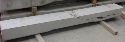
Figure 17: A sample of a Broken Concrete Tie
A mono-block crosstie is similar in dimension to a timber or wood crosstie and contains prestressing material embedded into the concrete. The prestressing material in the concrete is observed at the ends of most crosstie designs for proper tension position. Prestressed reinforced concrete crossties are made by tensioning the reinforcing material in a mold, then pouring cement concrete over the reinforcing material in the form. After the concrete cures, the tension on the reinforcing material is released, and transferred to the concrete which is already strong in compression. This allows the prestressed concrete to withstand both compressive and tensile loads. If the concrete spalls, or if the prestressing material is otherwise allowed to lose bond with the concrete, the prestressing material is no longer in tension. A concrete crosstie’s flexural strength is lost when the prestress force is reduced through corrosion, concrete deterioration, or poor bond with the concrete due to improper manufacturing or deterioration. The prestressing material may corrode if insufficient concrete cover or concrete cracking allows the intrusion of moisture and oxygen. When this happens, the once prestressed concrete crosstie can no longer withstand tensile loads, and it could fail in service.
Alternatively, post-tensioned mono-block concrete crossties are made by tensioning the reinforcement after the concrete has been cast. In this case, the post-tensioning forces are primarily transferred to the concrete through anchorage elements rather than direct bonding between the tensioning elements and the concrete.
Prestressing material is often exposed in a concrete crosstie as a crack or spall, but it can also be exposed on the side of the tie. When prestressing material becomes exposed on the side of a crosstie, the prestressing material may no longer be in tension, the prestressed concrete can no longer withstand the tensile loads and can structurally fail. This does not apply to reinforcing material left visible at the end of the crosstie during the manufacturing process.
The compressive strength of the concrete material and the amount of prestress applied in the manufacturing process provide the strength and stiffness necessary to adequately support and distribute wheel loads to the subgrade. The prestressing material encased in concrete hold the crosstie together and provides tensile strength. However, significant cracking or discernible deterioration exposure of the reinforcing strands to water and oxygen could produce loss of the prestress force through corrosion, concrete deterioration, and poor bonding. Loss of the prestress force renders the crosstie susceptible to structural failure and as a consequence, stability failure relating to track geometry noncompliance.
Crossties transversely broken between the rail seats and showing signs of further deterioration (loss of tension in prestressing material—upper and lower levels of exposure to metal wires or strands) constitute failure. This means that there cannot be a complete separation of the concrete material making up the crosstie.
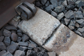
Figure 18: Crosstie Transversely Broken Between the Rail Seats
Crosstie failure is exhibited in three distinct ways: stress induced breaks, cracks; mechanical abrasion; or chemical decomposition. These conditions in small or large degrees compromise the crosstie’s ability to maintain proper gage, alignment, and track surface. Walking inspections would demonstrate clearly visible spalls, chips, cracks, and similar breaks. However, the compression of prestressed concrete crossties may close cracks as they occur, making them difficult to observe. Such closed cracks, if oriented vertically and located near the center of the crosstie, may weaken the crossties if the tie is center bound.
Disregarding chemical attack and freeze-thaw cracking, breaks or cracks are divided into three general conditions: longitudinal cracks, center cracks, and rail seat cracks.
• Longitudinal cracks are horizontal through the crosstie and extend parallel to its length. They can be initiated by high impacts on one or both sides of the rail bearing inserts, even though they are more commonly associated with design, materials, and manufacturing aspects of crossties.
• Crosstie center cracks are vertical cracks extending transversely (across) the crosstie. These cracks are the result of high negative bending movement (usually center bound), originating at the crosstie top and extending downward. The condition could be progressive, and adjacent crossties might be affected.
• Rail seat cracks are vertical cracks that are not easily visible. They usually extend from the bottom of the crosstie on one or both sides of the crosstie and are often hard to detect. It is possible for a crosstie to be broken through, but, due to the location of the break, the prestressing material may not be visible.
Crosstie strength, generally, is not significantly impacted if a crack only extends through the top layer of the prestressing material without exposing it. However, once the crack extends beyond the top layer, there can be a loss of prestressing material and concrete bond strength.
Paragraph (d)(2) makes clear that crossties counted to fulfill the requirements of paragraph (b) of this section must not be deteriorated or broken off in the vicinity of the shoulder or insert so that the fastener assembly can either pull out or move laterally more than three eighths inch relative to the crosstie, as these conditions weaken rail fastener integrity.
Paragraph (d)(3) provides that a crosstie counted to fulfill the requirements of (b) must not be deteriorated such that the base of either rail can move laterally more than three-eighths inch relative to the crosstie on curves of 2 degrees or greater; or can move laterally more than one-half inch relative to the crosstie on tangent track or curves of less than 2 degrees. This section allows for a combination rail movement, inward and outward, up to the dimensions specified, but not separately for each rail. The rail and fastener assembly work as a system capable of providing electrical insulation, adequate resistance to lateral displacement, undesired gage widening, rail canting, rail rollover, and abrasive or excessive compressive stresses. In accordance with policy and procedures, inspectors are encouraged to use the assigned PTLF in assessing the amount of lateral rail movement, wherever applicable.
Paragraph (d)(4) requires that crossties counted to fulfill the requirements of paragraph (b) of this section must not be deteriorated or abraded at any point under the rail seat to a depth of one-half inch or more. The measurement of one-half inch includes depth from the loss of rail pad material. The importance of having pad material in place with sufficient hysteresis (i.e., resilience (elasticity) to dampen high impact loading and recover) is paramount to control rail seat cracks caused by rail surface defects, wheel flats, or out of round wheels. Additionally, concrete crossties must be capable of providing adequate rail longitudinal restraint from excessive rail creepage or thermally induced forces or stress. “Rail creepage” is the tractive effort or pulling force exerted by a locomotive or car wheels, and “thermally induced forces or stress” is the longitudinal expansion and contraction of the rail, creating either compressive or tensile forces as the rail temperature increases or decreases, respectively. The loss of pad material causes a loss of toeload force, which may decrease longitudinal restraint. See the following figure. Note: inward or outward rail cant angle conventions are interchangeable among geometry measurement systems. FRA geometry cars record inward cant as positive, and outward cant as negative.
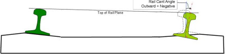
Figure 19: Positive and Negative Cant
Paragraph (d)(5) requires that crossties counted to fulfill the requirements of paragraph (b) of this section must not be deteriorated such that the crosstie’s fastening or anchoring system including rail anchors is unable to maintain longitudinal rail restraint, maintain rail hold down, or maintain gage, due to insufficient fastener toeload. Inspectors evaluate crossties individually by “definitional and functional” criteria. A compliant crosstie is demonstrated when a 39-foot track segment maintains safe track geometry and structurally supports the imposed wheel loads. In addition to ballast, anchors bear against the sides of crossties to control longitudinal rail movement, and certain types of fasteners also act to control rail movement by exerting a downward clamping force (toeload) on the upper rail base. Part of the complexity of crosstie assessment is the fastener component. Both crossties and fasteners act as a system to deliver the expected performance effect. A noncompliant crosstie and defective fastener assembly improperly maintains the rail position and support in the rail seat and contributes to excessive lateral gage widening (rail cant-rail rollover), and longitudinal rail movement because of loss of toeload.
Fastener assemblies or anchoring systems allow a certain amount of rail movement through the crosstie to effectively relieve rail creepage (tractive and thermal force build up). However, because of the unrestrained buildup caused by rail creep, the longitudinal expansion and contraction of the rail creates either compressive or tensile forces, respectively. When longitudinal rail movement is ‘uncontrolled,’ it may disturb the track structure, causing misalignment (compression) or pull-apart (tensile) conditions to catastrophic failure. Specific longitudinal performance metrics would be undesirable and restrict certain fastener assembly designs and capabilities to control longitudinal rail movement. Therefore, inspectors must use good judgment in determining fastener assembly and crosstie effectiveness.
Paragraph (d)(6) makes clear that crossties counted to fulfill the requirements of paragraph (b) of this section must not be configured with less than two fasteners on the same rail, except as provided in § 213.127(c), which includes requirements specific to fasteners used in conjunction with concrete crossties. As with nonconcrete ties, one of the safety requirements of an effective concrete tie is its ability to hold fasteners.
109(e) Class 1 and 2 track shall have one crosstie whose centerline is within 24 inches of each rail joint (end) location. Class 3, 4, and 5 track shall have either one crosstie whose centerline is within 18 inches of each rail joint location or two crossties whose centerlines are within 24 inches either side of each rail joint location. The relative position of these crossties is described in the following three diagrams:
(1) Each rail joint in Classes 1 and 2 track shall be supported by at least one crosstie specified in paragraph (c) and (d) of this section whose centerline is within 48 inches as shown in Figure 1.
Classes 1 and 2
24″ Defective
48″
Figure 1
(2) Each rail joint in Class 3, 4, and 5 track shall be supported by either at least one crosstie specified in paragraphs (c) and (d) of this section whose centerline is within 36 inches as shown in Figure 2, or:
Classes 3 through 5
18″ Defective
36″
Figure 2
(3) Two crossties, one on each side of the rail joint, whose centerlines are within 24 inches of the rail joint location as shown in Figure 3.
Classes 3 through 5
24″
24″
48″
Figure 3
Guidance: A nondefective joint tie must be found within the prescribed distance of the centerline of the joint measured at the rail end. In Classes 3 through 5, joint tie placement can be satisfied by either a one tie configuration, or by a two-tie configuration.
For clarity of measurement and description:
Where a short piece of rail only inches in length is inserted between the rail ends and incorporated into the joint bar assembly, measure from the bar centerline. Also see § 213.121(d), Rail Joints.
Where nonsymmetrical bars exist, (e.g., five-hole heel block bars, five-hole compromise bars) measure from the design point where rail ends normally abut.
109(f) For track constructed without crossties, such as slab track, track connected directly to bridge structural components, track over servicing pits, etc., the track structure shall meet the requirements of paragraph (b)(1) of this section.
Guidance: This paragraph addresses track constructed without crossties or bridge timbers, such as concrete-slab track, in which running rails are secured through fixation to another structural member.
In general, discrepancies may arise in evaluation of crosstie conditions, if decisions are based only on an inspector’s maintenance experience, which varies widely among the inspectors. Inspectors should evaluate tie condition solely on the basis of the definitions provided in this section. Each crosstie must be evaluated individually by these criteria. As with all provisions of the TSS, the inspector must use judgment and discretion in the application of the crosstie standards. They should be used to describe conditions that constitute a risk to the safe operation of trains, and should not be applied in doubtful cases.
Gage rods are not an effective substitute for a proper crosstie and rail-fastening system. Gage rods can be subject to sudden failure, they provide no vertical rail support, and they provide no resistance to rail roll-over forces. However, gage rods may be installed when they are used as a secondary means of support for maintaining gage. Where gage rods are used and it is obvious that the condition of the crosstie and fastening system in the immediate vicinity is incapable of maintaining adequate gage, then the inspector should consider citing a crosstie or fastener defect.
Certain crossties may not be able to hold spikes or rail fasteners in their present condition. In these cases, it may be possible to bring the crossties into compliance by either plugging and re-spiking, or adding additional rail-holding or plate-holding spikes, or both.
Where conditions are closer to a rail-fastener issue (e.g., sound ties in track are not fastened to the rail), inspectors should refer to the guidance under § 213.127.
| § 213.110 Gage Restraint Measurement Systems |
110(a) A track owner may elect to implement a Gage Restraint Measurement System (GRMS), supplemented by the use of a Portable Track Loading Fixture (PTLF), to determine compliance with the crosstie and fastener requirements specified in §§ 213.109 and 213.127 provided that–
(1) The track owner notifies the appropriate FRA Regional office at least 30 days prior to the designation of any line segment on which GRMS technology will be implemented; and
(2) The track owner notifies the appropriate FRA Regional office at least 10 days prior to the removal of any line segment from GRMS designation.
Guidance: This paragraph provides for the implementation of a GRMS, supplemented by the use of a PTLF, to determine compliance with the crosstie and rail fastener requirements specified in §§ 213.109 and 213.127. Track owners electing to implement this technology must provide the appropriate FRA office (Track and Structures Division) with notification that specifically identifies the line segments where GRMS will be used.
The notification must be provided to FRA at least 30 days prior to the designation of any line segment which will be subject to the requirements of this section. Even though the notification requirement is satisfied, and the GRMS vehicle is determined to meet the minimum design requirements, the actual “triggering event,” which places the line segment under the GRMS requirements, is the initial track survey with the GRMS vehicle.
Track owners must also provide FRA with at least 10 days’ notice prior to the removal of a line segment from GRMS designation. This requirement provides FRA with advance notice of the criteria change for the inspection of crossties and fasteners and places some control over the random removal of line segments from GRMS designation.
110(b) Initial notification under paragraph (a)(1) of this section shall include–
(1) Identification of the line segment(s) by timetable designation, milepost limits, class of track, or other identifying criteria; and
(2) The most recent record of million gross tons of traffic per year over the identified segment(s).
Guidance: This paragraph specifies what information track owners should include in their notifications to FRA about line segments designated for GRMS inspection. The information must include, at a minimum, the segment’s timetable designation, milepost limits, track class, million gross tons of traffic per year, and any other identifying characteristics of the segment.
For reasons of safety, GRMS vehicles have their split-axle in the retracted position when testing through special track work such as turnouts at grade rail-to-rail crossings (diamond), expansion joints, lift rail assemblies, etc. Where certain trackage within is not part of the designation, notifications should identify what and where these locations are and what distance approaching and leaving these locations are also excluded from GRMS designation. Locations excluded from GRMS designation will be subject to the requirements of §§ 213.109 and 213.127.
110(c)
(1) The track owner shall also provide to FRA sufficient technical data to establish compliance with the following minimum design requirements of a GRMS vehicle:
(2) Gage restraint shall be measured -between the heads of rail—
(i) At an interval not exceeding 16 inches;
(ii) Under an applied vertical load of no less than 10 kips per rail; and
(iii) Under an applied lateral load that provides for a lateral/vertical load ratio of between 0.5 and 1.25, 0and a load severity greater than 3 kips but less than 8 kips per rail.
5 GRMS equipment using load combinations developing L/V ratios that exceed 0.8 shall be operated with caution to protect against the risk of wheel climb by the test wheelset.
Guidance: This paragraph describes minimum design requirements for GRMS vehicles. Track owners must submit to FRA sufficient technical data so that the agency can establish whether the track owner is in compliance with these design requirements. This paragraph requires that gage must be measured between the heads of the rail at an interval not exceeding 16 inches. The paragraph provides for design flexibility by establishing acceptable ranges for the lateral/vertical load ratio and the resulting lateral load severity, both of which can be satisfied by various load configurations, provided that the applied vertical load is not less than 10 kips per rail.
The rule provides for design flexibility by establishing acceptable ranges for various loading requirements. These ranges are considered absolute, and loading configurations that fall outside of the prescribed ranges will not be considered acceptable. Some loading configurations may develop high lateral/vertical load ratios and therefore lubrication of the gage face of the rail ahead of the split axle may be required to reduce the coefficient of friction to prevent wheel climb. Footnote 5 to this section cautions operations at L/V ratios exceeding 0.8 to protect against the risk of wheel climb by the test wheelset. This footnote is identical to footnote 5, which applies to § 213.333, Automated vehicle-based inspection systems, to ensure conformity between this section and its Subpart G counterpart.
110(d) Load severity is defined by the formula:
S= L – cV
Where
S = Load severity, defined as the lateral load applied to the fastener system (kips). L = Actual lateral load applied (kips).
c = Coefficient of friction between the rail/tie, which is assigned a nominal value of 0.4.
V = Actual vertical load applied (pounds), or static vertical wheel load if vertical load is not measured.
Guidance: This paragraph prescribes a formula for the calculation of “load severity” required by 110(c)(2) iii. The coefficient of friction at rail/tie interface can change the load severity level when the applied actual lateral and vertical loads are given. However, it is impractical to determine the actual coefficients of friction, which vary from place to place in the GRMS territory. A nominal value of 0.4 can always be used.
110(e) The measured gage values shall be converted to a Projected Loaded Gage 24 (PLG 24) as follows–
PLG 24 = UTG + A × (LTG – UTG)
Where –
UTG = Unloaded track gage measured by the GRMS vehicle at a point no less than 10- feet from any lateral or vertical load application.
LTG = Loaded track gage measured by the GRMS vehicle at a point no more than 12 inches from the lateral load application point.
A = The extrapolation factor used to convert the measured loaded gage to expected loaded gage under a 24-kip lateral load and a 33-kip vertical load.
For all track –
513.13
A⋅−⋅−⋅− =
( ) ( )2 258.0009.258.0
L V L V
Note: The A factor shall not exceed a value of 3.184 under any valid loading configuration. L = Actual lateral load applied (kips).
V = Actual vertical load applied (kips), or static vertical wheel load if vertical load is not measured.
Guidance: This paragraph prescribes the formula for the calculation of the projected loaded gage 24 (PLG 24). The formula provides a method to normalize the PLG regardless actual lateral load loads applied by different GRMS systems. Accurate measurements of unloaded gage, GRMS loaded gage, and the lateral load applied are of critical importance because these measurements are used in the calculation of PLG 24 values which constitute a direct measure of track strength.
To minimize the influence from adjacent loads, the unloaded track gage (UTG) must be measured by the GRMS vehicle at a point no less than 10 feet from any lateral or vertical load application and the loaded track gage (LPG) at a point no more than 12 inches from the lateral load application point.
110(f) The measured gage and load values shall be converted to a Gage Widening Projection (GWP) as follows:
26.8
( ) L V
GWP LTG UTG⋅−
⋅−=258.0
Guidance: This paragraph prescribes the formula for the calculation of the gage widening projection (GWP). The GWP is intended to compensate for the weight of the testing vehicle. Use of the GWP is supported by research results documented in the report titled “Development of Gage Widening Projection Parameter for the Deployable Gage Restraint Measurement System” (DOT/FRA/ORD-06/13, October 2006), which is available on FRA’s website.
By making the criteria in this section consistent with those in § 213.333 in Subpart G, the rule makes it easier for a track owner or railroad to comply with GRMS requirements regardless of the class of track.
110(g) The GRMS vehicle shall be capable of producing output reports that provide a trace, on a constant-distance scale, of all parameters specified in paragraph (l) of this section.
110(h) The GRMS vehicle shall be capable of providing an exception report containing a systematic listing of all exceptions, by magnitude and location, to all the parameters specified in paragraph (l) of this section.
110(i) The exception reports required by this section shall be provided to the appropriate person designated as fully qualified under § 213.7 prior to the next inspection required under § 213.233.
Guidance: Paragraphs (g), (h), and (i) require that GRMS vehicles be capable of producing a stripchart of all the parameters specified in paragraph (l) of this section, as well as a printed exception report listing, by magnitude and location, all exceptions from these parameters. The exception report listing must be provided to the appropriate persons designated as fully qualified under § 213.7 prior to the next inspection required under § 213.233 of the TSS.
Since the premise behind GRMS technology is to identify areas of weak gage restraint that either need immediate attention or must be continually monitored until the next GRMS inspection, the exception report listing must be retained and be available for review by the § 213.7 inspection personnel. FRA inspectors will obtain, or have access to, this exception report when conducting regular compliance inspections over GRMS designated line segments.
110(j) The track owner shall institute the necessary procedures for maintaining the integrity of the data collected by the GRMS and PTLF systems. At a minimum, the track owner shall–
(1) Maintain and make available to the Federal Railroad Administration documented calibration procedures on each GRMS vehicle which, at a minimum, shall specify a daily instrument verification procedure that will ensure correlation between measurements made on the ground and those recorded by the instrumentation with respect to loaded and unloaded gage parameters; and
(2) Maintain each PTLF used for determining compliance with the requirements of this section such that the 4,000-pound reading is accurate to within five percent of that reading.
Guidance: This paragraph requires the track owner to institute procedures to ensure the integrity of data collected by the GRMS and PTLF systems. Track owners must maintain documented calibration procedures on each GRMS vehicle and make them available upon request from an FRA representative. A daily instrument verification procedure is required to ensure that measurements of loaded and unloaded gage recorded by the instrumentation correlate to actual field measurements. Track owners must also develop and implement the necessary PTLF inspection and maintenance procedures so that the 4,000-pound reading is accurate within plus or minus 5 percent.
110(k) The track owner shall provide training in GRMS technology to all persons designated as fully qualified under § 213.7 and whose territories are subject to the requirements of this section. The training program shall be made available to the Federal Railroad Administration upon request. At a minimum, the training program shall address–
(1) Basic GRMS procedures;
(2) Interpretation and handling of exception reports generated by the GRMS vehicle;
(3) Locating and verifying defects in the field;
(4) Remedial action requirements;
(5) Use and calibration of the PTLF; and
(6) Recordkeeping requirements.
Guidance: This paragraph recognizes the need for persons designated as fully qualified under § 213.7, and whose territories are subject to the requirements of this section, to receive training on the implementation of GRMS technology. The track owner therefore is required to develop a formal GRMS training program that must be made available to FRA upon request. The training of affected employees is another “triggering event” that must be satisfied prior to a line segment being designated as GRMS territory under this section.
The training program must provide detailed instruction on the specific areas identified in this paragraph. In particular, the training must address basic GRMS operational procedures, interpretation and handling of exception reports, how to locate and verify GRMS defects in the field, remedial action requirements to be initiated when defects are verified, how to use and calibrate the PTLF, and the recordkeeping requirements associated with the implementation of GRMS technology.
The requirement for GRMS training applies to fully qualified § 213.7 personnel under paragraphs (a) and (b) who are going to be subject to the requirements of this section. This is not to say that all fully qualified § 213.7 personnel need this training (e.g., welder foreman, production gang foreman, etc.). It is also not necessary for all fully qualified § 213.7 personnel who receive the GRMS training to be issued PTLFs. However, if circumstances arise where they need a PTLF, they should have access to one and be trained in how to use it and interpret the results.
The track owner must also take into consideration any relief personnel, newly qualified personnel, or personnel transferred from non-GRMS territory into a GRMS territory, which will be subject to the GRMS requirements. These personnel must be provided with sufficient instructions and training that enable them to demonstrate to the track owner that they know and understand the requirements of this section.
110(l) The GRMS record of lateral restraint shall identify two exception levels. At a minimum, the track owner shall initiate the required remedial action at each exception level as defined in the following table–
| GRMS1 parameters | If measurement value exceeds | Remedial action required |
| First Level Exception | ||
| UTG…… | 58 inches…… | (1) Immediately protect the exception location with a 10 m.p.h. speed restriction, then verify location; (2) Restore lateral restraint and maintain in compliance with PTLF criteria as described in paragraph (m) of this section; and (3) Maintain compliance with § 213.53(b) as measured with the PTLF. |
| LTG……. | 58 inches…… | |
| PLG24…. | 59 inches…… | |
| GWP…… | 1 inch…… | |
| Second Level Exception | ||
| LTG…… PLG24…… | 57 ¾ inches on Class 4 and 5 track2…… | (1) Limit operating speed to no more than the maximum allowable under § 213.9 for Class 3 track, then verify location; (2) Maintain in compliance with PTLF criteria as described in paragraph (m) of this section; and (3) Maintain compliance with § 213.53(b) as measured with the PTLF. |
| 58 inches…… | ||
| GWP…… | 0.75 inch…… | |
1 Definitions for the GRMS parameters referenced in this table are found in paragraph (p) of this section.
2 This note recognizes that good track will typically increase in total gage by as much as one quarter of an inch due to outward rail rotation under GRMS loading conditions. For Class 2 and 3 track, the GRMS LTG values are also increased by one-quarter of inch to a maximum of 58 inches. However, for any class of track, GRMS LTG values in excess of 58 inches are considered First Level exceptions and the appropriate remedial action(s) must be taken by the track owner. This 1/4-inch increase in allowable gage applies only to GRMS LTG. For gage measured by traditional methods, or with the use of the PTLF, the table in § 213.53(b) applies.
Guidance: The VTI final rule has corrected the table to renumber the remedial action specified for a second level exception. The remedial action has been designated as (1), (2), and (3) in the “Remedial action required” column, to be consistent with the remedial action specified for a first level exception. This paragraph specifies the parameters and threshold levels required to be reported as a record of lateral restraint following an inspection by a GRMS vehicle. The regulation requires that two levels of exceptions be reported during the GRMS inspection. Specific remedial actions are required for each level, as identified in the “Remedial action required” column. First level exceptions are required to be immediately protected by a 10 mph speed restriction until verification and corrective action can be instituted. Second level exceptions are to be monitored and maintained within the PTLF criteria outlined in paragraph (m) of this section.
The prior knowledge criterion is satisfied for those locations that are identified as first or second level exceptions on the record of lateral restraint which is generated following each GRMS inspection. Where field inspections conducted between GRMS inspections reveal an exception location that does not comply with either the track strength requirement or the gage requirement that are identified in paragraph (m) of this section, the inspector should consider recommending civil penalties. For locations that do not comply with the requirements of paragraph (m), and have not been identified on the record of lateral restraint as either a first or second level exception, the inspector shall exercise discretion to determine whether civil penalties should be recommended.
Footnote 2 in the table recognizes that typical good track will increase in total gage by as much as one-quarter inch due to outward rail rotation under GRMS loading conditions. Accordingly, for Class 2 and Class 3 track, the GRMS loaded track gage values are also increased by one-quarter inch to a maximum of 58 inches. GRMS loaded track gage values in excess of 58 inches must always be considered first level exceptions. This ¼-inch increase in gage applies only to GRMS loaded gage and does not apply to PTLF gage measurements or to measurements made by more traditional methods.
110(m) Between GRMS inspections, the PTLF may be used as an additional analytical tool to assist fully qualified § 213.7 individuals in determining compliance with the crosstie and fastener requirements of §§ 213.109 and 213.127. When the PTLF is used, whether as an additional analytical tool or to fulfill the requirements of paragraph (l), it shall be used subject to the following criteria–
(1) At any location along the track that the PTLF is applied, that location will be deemed in compliance with the crosstie and fastener requirements specified in §§ 213.109 and 213.127 provided that–
(i) The total gage widening at that location does not exceed ⅝ inch when increasing the applied force from 0 to 4,000 pounds; and
(ii) The gage of the track under 4,000 pounds of applied force does not exceed the allowable gage prescribed in § 213.53(b) for the class of track.
(2) Gage widening in excess of ⅝ inch shall constitute a deviation from Class 1 standards.
(3) A person designated as fully qualified under § 213.7 retains the discretionary authority to prescribe additional remedial actions for those locations, which comply with the requirements of paragraph (m)(1)(i) and (ii) of this section.
(4) When a functional PTLF is not available to a fully qualified person designated under § 213.7, the criteria for determining crosstie and fastener compliance shall be based solely on the requirements specified in §§ 213.109 and 213.127.
(5) If the PTLF becomes non-functional or is missing, the track owner will replace or repair it before the next inspection required under § 213.233.
(6) Where vertical loading of the track is necessary for contact with the lateral rail restraint components, a PTLF test will not be considered valid until contact with these components is restored under static loading conditions.
Guidance: While the remedial action table in paragraph (l) requires the use of the PTLF to measure compliance with the lateral restraint and gage requirements at identified exception
locations in GRMS territory, paragraph (m) also provides for the use of a PTLF as an additional analytical tool by fully qualified § 213.7 individuals at other locations in GRMS
territory. Paragraph (m) also describes the manner in which a PTLF must be used in GRMS territory, whether it is being used as an additional analytical tool or being used to meet the remedial action requirements set forth in paragraph (l). Compliance with
§§ 213.109 and 213.127 will be demonstrated when a PTLF is applied and (1) the total gage widening at that location does not exceed five-eighths inch when increasing the applied force from 0 to 4,000 pounds; and (2) the gage of the track measured under 4,000 pounds of applied force does not exceed the allowable gage prescribed in § 213.53(b) of this section for the class of track involved. Gage widening in excess of five-eighths inch shall constitute a deviation from Class 1 standards. At locations where compliance with the crosstie and rail fastener requirements have been demonstrated through the use of a PTLF, a fully qualified § 213.7 individual retains the discretionary authority to prescribe additional remedial actions, such as the placement of speed restrictions, if the individual deems it necessary. FRA inspectors will determine compliance with the crosstie and fastener requirements for gage restraint solely on the basis of the PTLF measurements. Where crossties are found to be so severely split or plate-cut to the extent that they are incapable of providing adequate vertical support, and conditions have degraded to the point where track surface conditions are approaching the allowable limit for the class of track, inspectors shall continue to consider writing a defect. In such a case use 213 defect code 0109B2, “crossties not effectively distributed to support a 39-foot segment of track.” Inspectors should record the track surface geometry condition as well as the contributing condition of the crossties in the description column. When a functional PTLF is not available to a fully qualified § 213.7 individual during a scheduled inspection under § 213.233 of this part, the track owner must repair or replace the PTLF prior to the next inspection required under § 213.233, or crosstie and rail fastener compliance will be based solely on the requirements specified in §§ 213.109 and 213.127.
At locations where crosstie or rail fastening compliance is questioned and vertical loading of the track structure is necessary to restore contact with the lateral rail restraint components, the crossties must be raised until lateral restraint contact is restored and a PTLF measurement must then be made.
If the track owner fails to immediately restore contact between the rail and the fastening system so that a valid PTLF test can be performed, this non-action will in effect remove this location from the GRMS standard and the inspector will determine compliance based on §§ 213.109 and 213.127.
Likewise, where gage rods have been installed which preclude a valid PTLF test to determine gage restraint of crossties and fasteners, this action will in effect remove the location from the GRMS standard and the inspector will determine compliance based on §§ 213.109 and 213.127.
110(n) The track owner shall maintain a record of the two most recent GRMS inspections at locations which meet the requirements specified in § 213.241(b). At a minimum, records shall
indicate the following–
(1) Location and nature of each First Level exception; and
(2) Nature and date of remedial action, if any, for each exception identified in paragraph (n)(1) of this section.
Guidance: This paragraph requires the track owner to maintain a record of the two most
recent GRMS inspections at locations meeting the requirements specified in § 213.241(b).
The records must indicate the location and nature of each First Level exception, and the
nature and date of initiated remedial action, if any, for each First Level exception. First
Level exceptions are described in the Remedial Action Table in paragraph (l).
The record required under paragraph (n) is also the official record of lateral restraint and
needs to identify both exception levels; however, the remedial action taken is required to
be shown only for First Level exceptions. Records will be maintained at locations that
meet the requirements specified in § 213.241(b).
110(o) The inspection interval for designated GRMS line segments shall be such that–
(1) On line segments where the annual tonnage exceeds two million gross tons, or where the maximum operating speeds for passenger trains exceeds 30 m.p.h., GRMS inspections must
be performed annually at an interval not to exceed 14 months; or
(2) On line segments where the annual tonnage is two million gross tons or less and the maximum operating speed for passenger trains does not exceed 30 m.p.h., the interval between GRMS inspections must not exceed 24 months.
Guidance: Paragraph (o) details the GRMS inspection requirements illustrated in the following table:
TRAFFIC GRMS INSPECTION INTERVAL If annual tonnage exceeds 2MGT, or passenger train speeds (if applicable) exceed
30 mph, then GRMS inspections must be performed
annually at an interval not to exceed 14 months [1]
If annual tonnage is 2MGT or less, and where passenger train speeds (if operated) do not exceed 30 mph, then The interval between GRMS inspections must not exceed 24 months [2]
[1] The maximum interval of 14 months is intended to provide some flexibility for scheduling when it may not be possible to schedule annual inspections within the same calendar month each year.
[2] This extended frequency is an attempt to make the technology more accessible to short line operators who may not have the financial or equipment resources available to larger railroads. For example, a GRMS inspection may be scheduled at up to 24-month
intervals if the railroad had 2 million annual tons or less and passenger trains were not authorized to operate at more than 30 mph.
Table 3: GRMS Inspection Requirements
110(p) As used in this section–
(1) Gage Restraint Measurement System (GRMS) means a track loading vehicle meeting the minimum design requirements specified in this section.
(2) Gage Widening Projection (GWP) means the measured gage widening, which is the difference between loaded and unloaded gage, at the applied loads, projected to reference loads of 16 kips of lateral force and 33 kips of vertical force.
(3) L/V ratio means the numerical ratio of lateral load applied at a point on the rail to the vertical load applied at that same point. GRMS design requirements specify an L/V ratio of between 0.5 and 1.25.
(4) Load severity means the amount of lateral load applied to the fastener system after frictionbetween rail and tie is overcome by any applied gage-widening lateral load.
(5) Loaded Track Gage (LTG) means the gage measured by the GRMS vehicle at a point no more than 12 inches from the lateral load application point.
(6) Portable Track Loading Fixture (PTLF) means a portable track loading device capable of applying an increasing lateral force from 0 to 4,000 pounds on the web/base fillet of each rail simultaneously.
(7) Projected Loaded Gage (PLG) means an extrapolated value for loaded gage calculated from actual measured loads and deflections. PLG 24 means the extrapolated value for
loaded gage under a 24,000 pound lateral load and a 33,000 pound vertical load.
(8) Unloaded Track Gage (UTG) means the gage measured by the GRMS vehicle at a point no less than 10-feet from any lateral or vertical load.
Guidance: This paragraph prescribes a list of definitions of terms essential to the implementation of GRMS technology.
§ 213.113 Defective rails
113(a) When an owner of track learns that a rail in the track contains any of the defects listed in the table contained in paragraph (c) of this section, a person designated under § 213.7 shall determine whether the track may continue in use. If the designated person determines that the track may continue in use, operation over the defective rail is not permitted until –
(1) The rail is replaced or repaired; or
(2) The remedial action prescribed in the table contained in paragraph (c) of this section is initiated.
113(b) When an owner of track learns that a rail in the track contains an indication of any of the defects listed in the table contained in paragraph (c) of this section, the track owner shall verify the indication. Except as provided in § 213.240, the track owner must verify the indication within four hours, unless the track owner has an indication of the existence of a defect that requires remedial action A, A2, or B identified in the table contained in paragraph (c) of this section, in which case the track owner must immediately verify the indication. If the indication is verified,
the track owner must–
(1) Replace or repair the rail; or
(2) Initiate the remedial action prescribed in the table contained in paragraph (c) of this section.
113(c) A track owner who learns that a rail contains one of the following defects shall prescribe the remedial action specified if the rail is not replaced or repaired, in accordance with this
paragraph’s table:
Notes:
A. Assign a person designated under § 213.7 to visually supervise each operation over the defective rail.
A2. Assign a person designated under § 213.7 to make a visual inspection. After a visual inspection, that person may authorize operation to continue without continuous visual supervision at a maximum of 10 m.p.h. for up to 24 hours prior to another such visual inspection or replacement or repair of the rail.
B. Limit operating speed over the defective rail to that as authorized by a person designated under § 213.7(a), who has at least one year of supervisory experience in railroad track
maintenance. The operating speed cannot be over 30 m.p.h. or the maximum allowable speed under § 213.9 for the class of track concerned, whichever is lower.
C. Apply joint bars bolted only through the outermost holes to the defect within 10 days after it is determined to continue the track in use. In the case of Class 3 through 5 track, limit the operating speed over the defective rail to 30 m.p.h. until joint bars are applied; thereafter, limit the speed to 50 m.p.h. or the maximum allowable speed under § 213.9 for the class of track concerned, whichever is lower. When a search for internal rail defects is conducted under § 213.237, and defects are discovered in Class 3 through 5 track that require remedial action C, the operating speed shall be limited to 50 m.p.h. or the maximum allowable speed under § 213.9 for the class of track concerned, whichever is lower, for a period not to exceed 4 days. If the
defective rail has not been removed from the track or a permanent repair made within 4 days of the discovery, limit operating speed over the defective rail to 30 m.p.h. until joint bars are
applied; thereafter, limit speed to 50 m.p.h. or the maximum allowable speed under § 213.9 for the class of track concerned, whichever is lower. When joint bars have not been applied within
10 days, the speed must be limited to 10 m.p.h. until joint bars are applied.
D. Apply joint bars bolted only through the outermost holes to the defect within 7 days after it is determined to continue the track in use. In the case of Class 3 through 5 track, limit operating
speed over the defective rail to 30 m.p.h. or less as authorized by a person designated under § 213.7(a), who has at least one year of supervisory experience in railroad track maintenance, until joint bars are applied; thereafter, limit speed to 50 m.p.h. or the maximum allowable speed under § 213.9 for the class of track concerned, whichever is lower. When joint bars have not
been applied within 7 days, the speed must be limited to 10 m.p.h. until the joint bars are applied.
E. Apply joint bars to the defect and bolt in accordance with § 213.121(d) and (e).
F. Inspect the rail within 90 days after it is determined to continue the track in use. If the rail remains in the track and is not replaced or repaired, the re-inspection cycle starts over with each
successive re-inspection unless the re-inspection reveals the rail defect to have increased in size and therefore become subject to a more restrictive remedial action. This process continues
indefinitely until the rail is removed from the track or repaired. If not inspected within 90 days, limit speed to that for Class 2 track or the maximum allowable speed under § 213.9 for the class of track concerned, whichever is lower, until it is inspected.
G. Inspect rail within 30 days after it is determined to continue the track in use. If the rail remains in the track and is not replaced or repaired, the re-inspection cycle starts over with each
successive re-inspection unless the re-inspection reveals the rail defect to have increased in size and therefore become subject to a more restrictive remedial action. This process continues
indefinitely until the rail is removed from the track or repaired. If not inspected within 30 days, limit speed to that for Class 2 track or the maximum allowable speed under § 213.9 for the class of track concerned, whichever is lower, until it is inspected.
H. Limit operating speed over the defective rail to 50 m.p.h. or the maximum allowable speed under § 213.9 for the class of track concerned, whichever is lower.
I. Limit operating speed over the defective rail to 30 m.p.h. or the maximum allowable speed under § 213.9 for the class of track concerned, whichever is lower.
113(d) As used in this section—
(1) Bolt hole crack means a crack across the web, originating from a bolt hole, and progressing on a path either inclined upward toward the rail head or inclined downward toward the base. Fully developed bolt hole cracks may continue horizontally along the head/web or base/web fillet, or they may progress into and through the head or base to separate a piece of the rail end from the rail. Multiple cracks occurring in one rail end are considered to be a single defect. However, bolt hole cracks occurring in adjacent rail ends within the same joint must be reported as separate defects.
(2) Broken base means any break in the base of the rail.
(3) Compound fissure means a progressive fracture originating from a horizontal split head that turns up or down, or in both directions, in the head of the rail. Transverse development
normally progresses substantially at a right angle to the length of the rail.
(4) Crushed head means a short length of rail, not at a joint, which has drooped or sagged
across the width of the rail head to a depth of 3⁄8 inch or more below the rest of the rail head and 8 inches or more in length. Unlike flattened rail where the depression is visible on the
rail head only, the sagging or drooping is also visible in the head/web fillet area.
(5) Damaged rail means any rail broken or otherwise damaged by a derailment, broken, flat, or unbalanced wheel, wheel slipping, or similar causes.
(6) Defective weld means a field or plant weld containing any discontinuities or pockets, exceeding 5 percent of the rail head area individually or 10 percent in the aggregate, oriented in or near the transverse plane, due to incomplete penetration of the weld metal between the rail ends, lack of fusion between weld and rail end metal, entrainment of slag or sand, under-bead or shrinkage cracking, or fatigue cracking. Weld defects may originate in
the rail head, web, or base, and in some cases, cracks may progress from the defect into either or both adjoining rail ends. If the weld defect progresses longitudinally through the weld section, the defect is considered a split web for purposes of remedial action required by this section.
(7) Detail fracture means a progressive fracture originating at or near the surface of the rail head. These fractures should not be confused with transverse fissures, compound fissures, or
other defects which have internal origins. Detail fractures may arise from shelled spots, head checks, or flaking.
(8) Engine burn fracture means a progressive fracture originating in spots where driving wheels have slipped on top of the rail head. In developing downward these fractures frequently resemble the compound or even transverse fissures with which they should not be confused or classified.
(9) Flattened rail means a short length of rail, not at a joint, which has flattened out across the width of the rail head to a depth of 3⁄8 inch or more below the rest of the rail and 8 inches or more in length. Flattened rail occurrences have no repetitive regularity and thus do not include corrugations, and have no apparent localized cause such as a weld or engine burn. Their individual length is relatively short, as compared to a condition such as head flow on the low rail of curves.
(10) Head and web separation means a progressive fracture, longitudinally separating the head from the web of the rail at the head fillet area.
(11) Horizontal split head means a horizontal progressive defect originating inside of the rail head, usually 1⁄4 inch or more below the running surface and progressing horizontally in all directions, and generally accompanied by a flat spot on the running surface. The defect appears as a crack lengthwise of the rail when it reaches the side of the rail head.
(12) Ordinary break means a partial or complete break in which there is no sign of a fissure, and in which none of the other defects described in this paragraph (d) is found.
(13) Piped rail means a vertical split in a rail, usually in the web, due to failure of the shrinkage cavity in the ingot to unite in rolling.
(14) Split web means a lengthwise crack along the side of the web and extending into or through it.
(15) Transverse fissure means a progressive crosswise fracture starting from a crystalline center or nucleus inside the head from which it spreads outward as a smooth, bright, or dark round or oval surface substantially at a right angle to the length of the rail. The
distinguishing features of a transverse fissure from other types of fractures or defects are the crystalline center or nucleus and the nearly smooth surface of the development which surrounds it.
(16) Vertical split head means a vertical split through or near the middle of the head, and extending into or through it. A crack or rust streak may show under the head close to the web or pieces may be split off the side of the head.
Guidance: In paragraph (a), FRA explains that only a person qualified under § 213.7 is able to determine that a track may continue to be used once a defective rail (as defined in
this section) is identified, regardless of the method by which it was identified.
The option “or repaired” in paragraph (a)(1) allows railroads to use recently developed rail head removal and replacement processes to remove just the defective portion of the rail section. This process is used to remove transverse defects or some types of defective welds, by using recently developed weld technologies. These processes, when used correctly, allow the remaining non-defective portion of the rail to remain in the track. Paragraph (b) provides that track owners have up to a 4-hour period (except as provided in section 213.240 – Continuous Testing) in which to verify that certain suspected defects exist in a rail section, once they learn that the rail indicates any of the defects identified in
paragraph (c)’s remedial action table. This 4-hour deferred verification period applies only to suspected defects that may require remedial action Notes “C” through “I,” found in the
remedial action table. This 4-hour period does not apply to suspected defects that may require remedial action Notes “A,” “A2,” or “B,” which are more serious and must be verified immediately. The 4-hour timeframe provides flexibility to allow the rail flaw detector car to continue testing in a limited non-stop mode, without requiring verification of less serious, suspected
defects that may require remedial action under notes “C” through “I.” This flexibility also helps to avoid the need to operate the detector car in a non-test, “run light” mode over a possibly severe defective rail condition that could cause a derailment, when having to clear the track for traffic movement. However, any suspected defect encountered that may require remedial action notes “A,” “A2”, or “B” requires immediate verification. Overall,
the four-hour, deferred-verification period is intended to help to improve rail flaw detector car utilization, allow operation of the chase car test method, increase the opportunity to detect more serious defects, and ensure that entire rail a detector car is intended to travel over while in service is inspected.
Paragraph (c) contains both the remedial action table and its notes. The remedial actions required for defective rails are outlined based on circumstances and the time limits and
speeds are based on the severity of the defect. The intent is to provide a logical balance between preventing the likelihood for a rail failure and operational disruptions that negatively affect the movement of goods and people. The remedial actions also allow certain discretion to the track owner for the continued operation over certain defects. Inspectors should consider all rail defects dangerous and care should be taken to determine that proper remedial actions have been accomplished by the track owner of the railroad. When more than one defect is present in a rail, the defect requiring the most restrictive remedial action shall govern.
The remedial action table and specifications in the rule address the risks associated with rail failure. These risks are primarily dependent upon defect type and size and should not be dependent upon the manner or mechanism that reveals the existence of the defect. Failure of the track owner to comply with the operational (speed) restrictions, maintenance procedures, and the prescribed inspection intervals specified in this section and § 213.237 or § 213.240 may result in a violation of the TSS.
Note “A” clarifies that a person qualified to supervise certain renewals and inspect track as vdesignated in § 213.7 must visually supervise each operation over the defective rail. vote “A2” addresses mid-range transverse defect sizes. This remedial action allows for train operations to continue at a maximum of 10 mph for up to 24 hours, following a visual inspection by a person designated under § 213.7. If the rail is not repaired or replaced, another 24-hour cycle begins.
Note “B” limits the speed to that as authorized by a person designated under § 213.7(a) who has at least 1 year of experience in track maintenance. The qualified person has the responsibility to evaluate the rail defect and authorize the maximum operating speed over the defective rail based on the size of the defect and the operating conditions; however, the maximum speed over the rail may not exceed 30 mph or the maximum speed under § 213.9 for the class of track concerned (whichever is lower). This remedial action relies on the training, experience, and good judgement of the qualified person to appropriately determine what speed, if any, trains may safely be allowed to operate over a rail defect under this designation.
Notes “C,” “D,” and “H” limit the operating speed, following the application of joint bars, to 50 mph or the maximum allowable speed under § 213.9 for the class of track concerned (whichever is lower). When the maximum speed specified in Notes “B,” “C,” “D,” and “H” exceeds the current track speed, the railroad is still required to record that the defect exists, and what initial remedial action was applied. For example, when a railroad determines that remedial action Note “B” is required and the track speed already is 30 mph or less, the railroad must record the defect. This indicates that the railroad is aware of the characteristics of the defective rail and has designated a permissible speed in compliance with the regulation’s remedial actions. Note “C” applies specifically to detail fractures, engine burn fractures, transverse fissures, and defective welds, and addresses defects that are discovered during an internal rail inspection conducted per § 213.237 or § 213.240 and whose size is determined to be less than 25 percent of the rail head cross-sectional area.
Note “C” requires a track owner to apply joint bars bolted only through the outermost holes to the defect within 10 days after it is determined to continue the track in use. When joint bars have not been applied within 10 days, the track speed must be limited to 10 mph until joint bars are applied.
Note “D” applies specifically to detail fractures, engine burn fractures, transverse fissures, and defective welds, and addresses defects that are discovered during an internal rail inspection conducted per § 213.237 or § 213.240 and whose size is determined not to be equal to or greater than 60 percent of the rail head cross-sectional area.
Note “D” requires a track owner to apply joint bars bolted only through the outermost holes to the defect within 7 days after it is determined to continue the track in use. The allowance of 7 days provides the track owner with additional time for remediation when the defect is identified just prior to the start of weekend shutdown. When joint bars have not been applied within 7 days, the track speed must be limited to 10 mph until joint bars are applied. When an FRA inspector discovers a defective rail that requires the railroad representative to determine whether to continue the track in use and to designate the maximum speed
over the rail, the inspector should inquire as to the representative’s knowledge of the defect and remedial action. If the railroad was not aware of the defect prior to the FRA inspection, the FRA inspector should observe the actions taken by the railroad representative to determine compliance. If the railroad had previously found the defective rail, the FRA inspector should confirm the proper remedial action was taken. During records inspections, The FRA inspector should confirm that the defects were recorded and proper remedial actions were taken.
The remedial action table for defects failing in the transverse plane (transverse and compound fissures, detail and engine burn fractures, and defective welds) specifies a lower limit range base of 5 percent of the railhead cross-sectional area. If a transverse defect is reported to be less than 5 percent, the track owner is not required to provide corrective action under the TSS. Conditions reported to be less than 5 percent are not consistently found during rail breaking routines and therefore defect determination within this range is not always reliable. Compound fissure defects that weaken at least 5 but less than 70 percent of the cross-
sectional area of the rail head area are defects requiring remedial action (Note B). Defects equal to or greater than 70 but less than 100 percent of the cross-sectional head area require remedial action (Note A2), as prescribed. Defects that affect 100 percent of the cross- sectional head area require remedial action (Note A) as prescribed, the most restrictive remedial actions. Inspectors should be aware that compound fissures are defects that can
fail in the transverse or oblique plane and are characteristic of rail that has not been control-cooled (normally rolled prior to 1936).
Defects identified and grouped as detail fractures, engine burn fractures, transverse fissures, and defective welds, will weaken and will normally fail in the transverse plane. Their prescribed remedial action relates to a low range of at least 5 but less than 25 percent and a mid-range of at least 25 but less than 60 percent, for Notes “C” and “D,” respectively. Those defects require joint bar applications and operational speed restrictions within certain time frames. Defects extending less than 100 but at least 60 percent require a visual inspection. If the rail is not replaced, effectively repaired, or removed from service, an elective would be to restrict operation to a maximum of 10 mph for up to 24 hours, then
perform another visual inspection. The second part of remedial action Note “C,” starting with the second sentence, addresses
defects that are discovered in Classes 3 through 5 track during an internal rail inspection required under § 213.237, and which are less than 25 percent of the rail head cross-sectional area. For these specific defects, a track owner may operate for a period not to exceed 4 days, at a speed limited to 50 mph or the maximum allowable speed under § 213.9 for the class of track concerned, whichever is lower. If the defective rail is not removed or a permanent repair is not made within 4 days of discovery, the speed is limited to 30 mph for up to 10 days from discovery. If joint bars have not been applied within 10 days, speed shall be restricted to 10 mph until joint bars are applied or the rail is replaced. The requirements specified in this second part of remedial action Note “C” are intended to promote better usage of rail inspection equipment and therefore maximize the opportunity to discover rail defects, which are approaching service failure size. The results of FRA’s research indicate that defects of this type and size range have a predictable slow growth life. Research further indicates that even on today’s most heavily used trackage defects of
this type and size are unlikely to grow to service failure size in 4 days. In the remedial action table, all longitudinal defects are combined within one group subject to identical remedial actions based on their reported size. These types of longitudinal
defects all share similar growth rates and the same remedial actions are appropriate to each type. Defective rails categorized as horizontal split head, vertical split head, split web, piped rail,
and head-web separation, and defective weld (longitudinal) are longitudinal in nature.
When any of this group of defects is more than 1 inch, but not more than 2 inches, the remedial action initiated, under Note “H,” is to limit train speed to 50 mph, and Note “F” requires re-inspecting the rail in 90 days, if deciding operations will continue. If not inspected within 90 days, speeds must be limited to that for Class 2 track or the maximum allowable speed under § 213.9 for the class of track concerned, whichever is lower, until it is inspected. Defects in the range of more than 2 inches, but not more than 4 inches, require complying with Notes “I” and “G,” limiting speeds to 30 mph and requiring the rail be re-
inspected in 30 days, if the railroad track owner decides operations will continue. If not inspected within 30 days, speed is limited to that for Class 2 track or the maximum allowable speed under § 213.9 for the class of track concerned, whichever is lower, until it is inspected. When any of the six defect types exceed a length of 4 inches, remedial action Note “B” is required and speed must be limited to that authorized by a person designated
under § 213.7(a), but cannot exceed 30 mph or the maximum allowable under § 213.9 for the class of track concerned, whichever is lower.
A “bolt hole crack” is a progressive fracture originating at a bolt hole and extending away rom the hole, usually at an angle. It develops from high stress risers, usually initiating as a result of both dynamic and thermal responses of the joint bolt and points along the edge of the hole, under load. A major cause of this high stress is improper field drilling of the hole. Excessive longitudinal rail movement can also cause high stress along the edge of the hole.
Under Notes “H” and “F,” the remedial action for a bolt hole crack that is more than one-half of an inch, but not more than 1 inch, if the rail is not replaced, is to limit speed to 50 mph, or the maximum allowable under § 213.9 for the class of track concerned, whichever
is lower, then re-inspect the rail in 90 days, if operations will continue. For bolt hole cracks greater than 1 inch, but not exceeding 11⁄2 inches, Notes “H” and “G” apply. These rails are required to be limited to 50 mph, or the maximum allowable speed under § 213.9 for the class of track concerned, whichever is lower, and re-inspected within 30 days. For a bolt hole crack exceeding 11⁄2 inches, Note “B” applies and a person qualified under § 213.7(a) may elect to designate a speed restriction, which cannot exceed
30 mph, or the maximum allowable under § 213.9 for the class of track concerned, whichever is lower. Under Notes “F” and “G,” where corrective action requires rail to be re-inspected within a specific number of days after discovery, several options for compliance may be exercised depending on the nature of the defect. For those defects that are strictly internal and are not
yet visible to the naked eye, the only option would be to perform another inspection with rail flaw detection equipment, either rail-mounted or hand-held. For defects that are visible to the naked eye and therefore measurable, a visual inspection or an inspection with rail flaw detection equipment are acceptable options. For certain defects enclosed within the joint bar area, such as bolt hole cracks and head-web separations, the joint bars must be
removed if a visual re-inspection is to be made.
The re-inspection prescribed in Notes “F” and “G” must be performed prior to the expiration of the 30- or 90-day interval. If the rail remains in track and is not replaced or repaired, the re-inspection cycle starts over with each successive re-inspection unless the re-inspection reveals the rail defect to have increased in size and has therefore become subject to a more restrictive remedial action. This process continues indefinitely until the
rail is removed from track.
A broken base can result from improper bearing of the base on a track spike or tie plate shoulder, and from over crimped anchors, or it may originate in a manufacturing flaw. With today’s higher axle loads, inspectors can anticipate broken base defects in 75-pound, and smaller, rail sections with an irregular track surface, especially on the field side. For any broken base discovered that is more than 1 inch, but less than 6 inches in length, the remedial action (Note “D”) is to apply joint bars bolted through the outermost holes to the defect within 10 days, if operations will continue. In Classes 3 through 5 track, the operating speed must be reduced to 30 mph or less, as authorized by a person under § 213.7(a), until joint bars are applied. After that, operating speed is limited to 50 mph or the maximum allowable under § 213.9 for the class of track concerned, whichever is lower.
Under Notes “C” and “D,” there are several acceptable “outermost” bolting arrangements for joint bars centered on a rail defect. The Figure below illustrates acceptable bolting arrangements. In all cases, railroads may not drill a bolt hole next to a defect that is being remediated with the application of joints bars (pursuant to Notes “C” and “D”). The reason for not drilling next to the defect is to prevent the propagation of the crack into the hole closest to the defect.
Figure 20: Acceptable “outermost” Bolting Arrangements
A broken base in excess of 6 inches requires the assignment of a person designated under § 213.7 to visually supervise each train operation over the defective rail. The railroad may apply joint bars to the defect and bolt them in accordance with §§ 213.121(d) and (e), and thereafter must limit train operations to 30 mph or the maximum allowable under § 213.9 for the class of track concerned, whichever is lower. As reference, the dimensions between the outermost holes of a 24-inch joint bar vary between approximately 15 and 18 inches, and a 36-inch joint bar approaches 30 inches.
Inspectors should point out to the track owner that broken bases nearing these dimensions may negate the purpose for which the joint bars are applied. A broken base rail may be caused by damage from external sources, such as rail anchors being driven through the base by a derailed wheel. It is improper to consider them “damaged rail,” as this defect is addressed by more stringent provisions applicable to broken base rails, under Note “A,” or
Notes “E” and “I.” Damaged rail can result from flat or broken wheels, incidental hammer blows, or derailed or dragging equipment. Reducing the operational speed in Classes 3 through 5 track to 30 mph until joint bars are applied lessens the impact force imparted to the weaken area. Applying joint bars under Note “C” ensures a proper horizontal and vertical rail end alignment in the event the rail fails.
Flattened rails and crushed rails (localized collapsed head rail) are also caused by mechanical interaction from repetitive wheel loadings. FRA and industry research indicate that these occurrences are more accurately categorized as rail surface conditions, not internal rail defects, as they do not, in and of themselves, cause service failure of the rail. Although it is not a condition shown to affect the structural integrity of the rail section, it can result in less than desirable dynamic vehicle responses in the higher speed ranges. The flattened rail condition is identified in the table, as well as in the definition portion of
§ 213.113(b), as being three-eighths of an inch or more in depth below the rest of the rail head and 8 inches or more in length. As the defect becomes more severe by a reduced rail head depth, wheel forces increase.
The rule addresses flattened rail in terms of a specified remedial action for those of a certain depth and length. Those locations meeting the depth and length criteria must be limited to an operating speed of 50 mph or the maximum allowable under § 213.9 for the class of track concerned, whichever is lower.
“Break out in rail head” is defined as a piece that has physically separated from the parent rail. Rail defects meeting this definition are required to have each operation over the defective rail visually supervised by a person designated under § 213.7. Inspectors need to be aware that this definition has applicability across a wide range of rail defects, as indicated in the Remedial Action Table. Where rail defects have not progressed to the point where they meet the definition of a break out, but due to the type, length, and
location of the defect, they may present a hazard to continued train operations, inspectors should determine what remedial actions, if any, track owner should institute. The following are two rail head break out examples where the Note “A” corrective action
would be necessary:
Example One: A bolt hole break where the head of the rail is totally separated from the parent rail (either tight or loose), but that piece of rail will not physically lift out of the joint bars by hand. The inspector might determine that the separation was total because the separated piece rattled when tapped. It is important that railroads take the appropriate remedial action in this situation, because it is potentially very unsafe. It is impossible to
know what will happen when the next train operates over this defect. That train could cause the piece to become so loose that it comes out of place, cocks at an angle and causes a wheel to ramp up, derailing the train.
Example Two: A vertical split head defective rail where rail head separation is apparent because the inspector can determine that a physical separation has occurred through the rail head, but the rail head has not entirely separated over the entire length of the defect.
The following is an example where the Note “A” corrective action would not be necessary:
Example: At rail joints, a chipped rail end is not considered a rail defect according to the current § 213.113 table and should not be considered as a breakout in the rail head.
Some railroads in the past applied safety “weld straps” to thermite type field welds. These straps do not provide the same support of a joint bar. They would provide only limited support if a weld were to break under a train movement and, as such, they do not comply
with the provisions of corrective actions C, D, or E (installation of joint bars).
Figure 21: Weld Strap (Not allowed as corrective action for C, D, or E)
Only a joint bar having full contact with the bottom of the rail head and rail base [see § 213.121 (a)] that provides structural support, would comply with corrective actions C, D, or E, of this section so long as the rail has not fractured completely.
Figure 22: Weld Relief Bars (allowed for corrective action C, D, or E, unless the rail has broken)
Once the defective rail breaks, use of weld relief bars does not comply with the requirements of § 213.121(f), in that they do not adequately support the abutting rail ends. Therefore, these bars would not be an acceptable joint bar for joining two rail ends.
When an FRA inspector finds a rail defect that appears to originate from fatigue at a bond wire attachment weld, the inspector should cite the railroad for 213 defect code 0113B. Inspectors must also identify in their narrative the type of the rail defect (e.g., defective
weld, detail fracture, etc.). This defect code is related to placement of bond wire welds on the head of the rail just outside the joint bars, where untempered martensite associated with
the welds could lead to fatigue cracking that may rapidly progress to rail failure because of increased stresses.
FRA provides the Track Inspector Rail Defect Reference Manual on the e-library in its Web site. Inspectors are expected to be conversant with rail defect types, appearance, growth, hazards, and methods of detection.
§ 213.115 Rail end mismatch
Any mismatch of rails at joints may not be more than that prescribed by the following table –
Class of track
Any mismatch of rails at joints may not be more than the following-
On the tread of the rail ends
(inch)
On the gage side of the rail ends
(inch)
Class 1 track 1⁄4 1⁄4
Class 2 track 1⁄4 3
/16
Class 3 track 3
/16 3
/16
Class 4 and 5
track 1⁄8 1⁄8
Guidance: Use a straightedge to determine the mismatch by holding the straightedge longitudinally along the higher rail (tread) or along the gage side (five-eighths inch down from the running surface) of the rail. Measure the distance directly between the
straightedge and the rail. Disregard plastic overflow (gage side rail edge lipping), if any. One example of mismatch occurs when a section of a rail is placed in the track where the existing rail head is gage- and/or treadworn. Mismatch can also occur when the joint bars are loose. However, if the loose bars do not result in mismatch exceeding the thresholds under this section, report the defect as loose joint bars (see § 213.121).
The standards prescribe both tread and gage mismatch thresholds. A mismatch may result in high impact forces especially at higher speeds. If a mismatch in excess of the allowable results in significant rail end damage, a violation should be considered. Particular attention should be given to the mismatch on the gage side of a rail. A thin flange, skewed truck, or combination of both may cause a wheel to climb, particularly on the outer rail of a curve. The following figure shows the proper method to measure gage and tread mismatch.
Figure 23: Measuring Rail End Mismatch
§ 213.118 Continuous welded rail (CWR); plan review and approval.
118(a) Each track owner with track constructed of CW shall have in effect and comply with a plan that contains written procedures which address: the installation, adjustment, maintenance,
and inspection of CWR; inspection of CWR joints; and a training program for the application of those procedures.
118(b) The track owner shall file its CWR plan with the FRA Associate Administrator for Railroad Safety/Chief Safety Officer (Associate Administrator). Within 30 days of receipt of the submission, FRA will review the plan for compliance with this subpart. FRA will approve, disapprove or conditionally approve the submitted plan, and will provide written notice of its determination.
118(c) The track owner’s existing plan shall remain in effect until the track owner’s new plan is approved or conditionally approved and is effective pursuant to paragraph (d) of this section.
118(d) The track owner shall, upon receipt of FRA’s approval or conditional approval, establish the plan’s effective date. The track owner shall advise in writing FRA and all affected employees of the effective date.
118(e) FRA, for cause stated, may, subsequent to plan approval or conditional approval, require revisions to the plan to bring the plan into conformity with this subpart. Notice of a revision requirement shall be made in writing and specify the basis of FRA’s requirement. The track owner may, within 30 days of the revision requirement, respond and provide written submissions in support of the original plan. FRA renders a final decision in writing. Not more than 30 days
following any final decision requiring revisions to a CWR plan, the track owner shall amend the plan in accordance with FRA’s decision and resubmit the conforming plan. The conforming plan
becomes effective upon its submission to FRA. Guidance: All CWR plans must be submitted to FRA for review by the Track Division
and then approval by the Associate Administrator for Railroad Safety/Chief Safety Officer. FRA reviews each plan for compliance with § 213.119(a) through (l). District track specialists may be requested to provide recommendations concerning the
comprehensiveness of those procedures. Gage mismatch Tread mismatch straightedge ruler
When conducting track inspections, an FRA inspector should have with him the most
recent copy of a railroad’s CWR plan. This is important because it will enable the inspector
to perform a proper inspection and determine compliance with the plan. Finalized CWR
plans are posted on the FRA internal Track Department Library for the inspector’s review
and enforcement. If an inspector discovers substantial discrepancies between the official
plan on file with FRA and the plan in the field (or that there are substantial discrepancies
between the official plan on file with FRA and a railroad field manual), the inspector
should notify the district track specialist.
FRA may also conditionally approve a plan. There might be instances where it would be
beneficial for the agency to conditionally approve a plan. For example, FRA might decide
that a plan should be approved, but might need to look into new technology proposed in
the plan. FRA reserves the ability to later approve or disapprove a plan that it has formally
conditionally approved.
A track owner may update or modify CWR procedures as necessary, but must resubmit
any new or modified plan to FRA pursuant to § 213.118. Until the new plan is approved or
conditionally approved and effective pursuant to paragraph (d), the track owner’s existing
plan will remain in effect.
§ 213.119 Continuous welded rail (CWR); plan contents.
Guidance, General: In addition to safety-critical procedures listed in this section, the
railroad may decide to include procedures based on administrative or economic
considerations. For example, a railroad may choose to include instructions that limit the
use of worn secondhand replacement rail because of an economic concern about the length
of time that it might take to perform a satisfactory weld. The railroad may also include
specific actions in its procedures that are to be taken when installation or maintenance
work does not comply with its overall procedures.
Recording an activity that does not conform to the railroad’s CWR procedures does not
provide the railroad with indefinite relief from responsibility for compliance when its
procedures are not followed. Continued noncompliance may lead to an unsafe condition.
The recordkeeping procedure is intended to provide a safety net by flagging those activities
of noncompliance, which, if not brought into compliance in a timely manner, could lead to
an unsafe condition. For example, CWR installed in the winter months without adequate
rail anchors as prescribed by the written procedures and discovered in late summer would
clearly be a deficient condition, regardless of if it was recorded. When in doubt as to what
activities are considered safety related, the inspector should consult with the district track
specialist.
Whenever conducting inspections on a railroad and that activity includes observation of
CWR, FRA inspectors are to include only one “CWRP” unit on the header of their
Railroad Inspection System for Personal Computers (RISPC) inspection report. Record one
CWRP unit, regardless of the amount of CWR mileage inspected. Record the actual track
mileage units using the activity codes MTH, MTW, etc. When a defect is taken for any
aspect of § 213.119, FRA inspectors are to also designate CWRP for the line item
Track and Structures Compliance Manual Volume II, Chapter 1 – 2026
2.1.96
“activity” cell. In addition, inspectors are to use CWRP in each line item activity cell when
performing records inspections and recording deficiencies concerning CWR joint records.
The track owner shall comply with the contents of the CWR plan approved or conditionally
approved under § 213.118. The plan shall contain the following elements—
119(a) Procedures for the installation and adjustment of CWR which include—
(1) Designation of a desired rail installation temperature range for the geographic area in
which the CWR is located; and
(2) De-stressing procedures/methods which address proper attainment of the desired rail
installation temperature range when adjusting CWR.
Guidance: Track owners with track constructed of CWR are required to have in effect and
comply with a CWR plan. This includes track owners who operate entirely on CWR track
that has been designated as excepted track, pursuant to § 213.4. Pursuant to § 213.5(b), the
procedures under § 213.119 do not apply to excepted track.
Railroads typically establish a desired rail installation temperature range for the
geographical area that is higher than the annual mean temperature. This higher installation
temperature will account for the expected reduction of the force-free temperature caused
by track maintenance, train traffic, and other factors. As reference, the term for this
expected occurrence is “rail neutral temperature shift.” A railroad must establish a
designated installation temperature range for a specific territory under § 213.119(a)(1).
119(b) Rail anchoring or fastening requirements that will provide sufficient restraint to limit
longitudinal rail and crosstie movement to the extent practical, and specifically addressing CWR
rail anchoring or fastening patterns on bridges, bridge approaches, and at other locations where
possible longitudinal rail and crosstie movement associated with normally expected train-
induced forces, is restricted.
119(c) CWR joint installation and maintenance procedures which require that—
(1) Each rail shall be bolted with at least two bolts at each CWR joint;
Guidance: The track inspector should determine that any joints installed in CWR or
connecting to CWR must have at least two bolts in each rail end, a minimum of four bolts
installed in the joint bars, if not field welded at the time of installation. See § 213.121(e).
This requirement serves as a reminder to track owners that they cannot create their own
joint bolt requirements in their CWR plans that are less restrictive than those specified in
the TSS.
(2) In the case of a bolted joint installed during CWR installation after October 21, 2009, the
track owner shall either, within 60 days—
(i) Weld the joint;
Track and Structures Compliance Manual Volume II, Chapter 1 – 2026
2.1.97
(ii) Install a joint with six bolts; or
(iii) Anchor every tie 195 feet in both directions from the joint; and
Guidance: This section applies to major installations of CWR, such as more than 400 feet.
It is not intended for plug rails.
(3) In the case of a bolted joint in CWR experiencing service failure or a failed bar with a rail
gap present, the track owner shall either—
Guidance: This section addresses CWR joints that experience a failure with a rail gap
present. The definition of rail gap for this section is a gap that requires the assistance of
something other than a drift pin to reinstall bolts. An example of a joint failure with a rail
gap present is a joint where the rail ends could not be pulled back together manually, as
with the use of a drift pin; that is to say, mechanical or thermal assistance was needed to
close the gap and reinstall bolts. A remedial action from § 213.119(c)(3) must be taken.
Check for evidence of tension (such as bent and broken bolts) or application of thermal
force (heat from repair rope, sawdust, or flammable mix).
(i) Weld the joint;
Guidance: The rail is welded at the time the joint is repaired.
(ii) Replace the broken bar(s), replace the broken bolts, adjust the anchors and, within 30
days, weld the joint;
Guidance: The 30-day time limit is only to allow the railroad adequate time to gather
resources to weld the joint. If a CWR joint becomes battered before a repair can be
completed and the track owner decides to cut in a plug rail to remove the battered joint, the
track must immediately be brought into compliance as specified in § 213.121(e). The 30-
day time limit starts from the original joint installation date for both joints. The remedial
action 30-day period does not begin again when both CWR rail joints are required to be
removed. If the joints have not been welded on the 31st day, a violation may be submitted
to the track owner for failure to take the appropriate remedial action. The track owner must
have selected the planned remedial action to be taken on the inspection report or other
documentation that may be addressed in the CWR plan at the time the defect was
discovered, and it must be documented. This written or electronic documentation must be
made available upon request by FRA during regular business hours.
(iii) Replace the broken bar(s), replace the broken bolts, install one additional bolt per rail
end, and adjust anchors;
(iv) Replace the broken bar(s), replace the broken bolts, and anchor every tie 195 feet in both
directions from the CWR joint; or
(v) Replace the broken bar(s), replace the broken bolts, add rail with provisions for later
adjustment pursuant to paragraph (d)(2) of this section, and reapply the anchors.
Track and Structures Compliance Manual Volume II, Chapter 1 – 2026
2.1.98
Guidance: The track owner should ensure that any rail added during the repair of a CWR
pull-apart is properly adjusted back to the required safe neutral temperature in accordance
with the railroad’s CWR plan. As the rail temperature rises, the expansion of rail increases.
The track owner must have provisions in the CWR plan to slow order the affected track
and make repairs and adjustment to bring the track into compliance. For example, in many
cases, the addition of 1 inch of rail in a 1,000-foot string of CWR will lower its rail neutral
temperature by 13 degrees.
If the remedial actions, described in § 213.119(c)(iii), (iv), or (v) are used and the affected
joint fails again (with a rail gap present after the initial repair), additional, more restrictive
repairs are required. This shows that the rail tension was not adequately addressed during
the initial remedial action. CWR joints must be inspected for compliance with additional
parts of the TSS, such as tie condition, surface, rail end mismatch, and properly fitting joint
bars.
119(d) Procedures which specifically address maintaining a desired rail installation temperature
range when cutting CWR including rail repairs, in-track welding, and in conjunction with
adjustments made in the area of tight track, a track buckle, or a pull-apart. Rail repair practices
shall take into consideration existing rail temperature so that—
(1) When rail is removed, the length installed shall be determined by taking into consideration
the existing rail temperature and the desired rail installation temperature range; and
(2) Under no circumstances should rail be added when the rail temperature is below that
designated by paragraph (a)(1) of this section, without provisions for later adjustment.
119(e) Procedures which address the monitoring of CWR in curved track for inward shifts of
alinement toward the center of the curve as a result of disturbed track.
Guidance: Thermal and mechanical loads affecting track structure are decreased by the
track owner’s adherence to the track engineering standards. Adherence to the track owner’s
standards and the CWR plan promote CWR track stability and safety. Three engineering
elements resist mechanical loads and thermal loads: lateral resistance, longitudinal
resistance, and rail neutral temperature. Track buckles can be expected to occur
predominately in the lateral dimension. Lateral resistance is critical to being dependent
upon weight and size of crosstie material, ballast material type, shoulder width, crib
content, and its level of consolidation. As degree of curvature increases, the buckling
resistance decreases. A crosstie’s base, side (crib) friction, and ballast shoulder resistance
contribute to the overall lateral resistance sustained. In general, each contributes (base 50
percent, side 20–30 percent, and shoulder 20–30 percent) to this resistance, but the ratios
can vary depending on ballast condition. Lateral resistance varies in location depending on
the ballast shoulder geometry, crosstie size and type, and state of ballast consolidation.
Thermal loads, by themselves, can cause a buckle and are often called “static buckling.”
However, most buckling occurs under a combination of thermal and vehicle loads, termed
“dynamic buckling.” Inspectors should place emphasis on vehicle (dynamic) effects on
track lateral stability, where high rail temperatures and vehicle loading could progressively
Track and Structures Compliance Manual Volume II, Chapter 1 – 2026
2.1.99
weaken the track due to dynamic uplift (flexural waves) and a buckle mechanism response
induced by misalignment “growth.”
Because the majority of buckles occur under dynamic train movements, loading is an
important element in the buckling mechanism. Elements of track lateral instability include:
- Formation of initial track misalinement caused by reduced local resistance.
- High impact loads, initial rail surface (weld) imperfections, “soft” spots in ballast,
and curve (radial breathing) shifting. - Misalinement growth caused by high lateral loads, increased longitudinal forces,
track uplifts due to vertical loads, and train-induced vibration.
Inspectors may consider the above elements, combined with related evidence of actual
defects, geometry conditions, or other defective structural conditions, when evaluating the
adequacy of a railroad’s CWR stability procedures under § 213.119(b), (c), (d), and (e).
Locations where track buckling are more likely to occur include: horizontal and vertical
curves, bottom of grades, bridge approaches, highway-rail grade crossings, recently-
disturbed track, and areas of heavy train starting or braking.
The signs or precursors of buckles include:
- Newly formed alinement deviations: wavy, kinky, snaky, etc.
- Rails rotating or lifting out of the tie plates and intermittent loose tie plates.
- Excessive “running” rail causing ties to plow or churn the ballast.
- Insufficient anchors and anchors not installed tightly against the tie.
- Insufficient ballast section in the crib and shoulder areas.
- Gaps at crosstie ends, especially on the low (inner) rail.
Curves are more prone to buckling because of the curvature effect, alinement imperfection
sensitivity, and train loads. It is important for inspectors to consider when and where a
buckle may occur (e.g., on track segments where the CWR installation occurred below the
desired rail installation temperature range and there was inadequate control of the laying
temperature or inadequate adjustment of the rail afterwards). In addition, inspectors should
observe areas of recent maintenance involving either the ballast or rail, where there was
inadequate reconsolidating time for a disturbed ballast or inadequate temperature
adjustment when replacing a defective rail. As curvature increases, the buckling resistance
decreases. Under some conditions, high degree curvature can undergo gradual lateral shift
(progressive buckling). Lateral alinement deviations reduce the track buckling strength and
can initiate growth to critical levels. Vertical alinement deviations can also influence
buckling.
Track and Structures Compliance Manual Volume II, Chapter 1 – 2026
2.1.100
Lateral misalinement is an important consideration because it reduces the ability of the
track to resist buckling. An alinement offset or mid-ordinate within allowable limits may
“escalate” under the imposed loads. This is called “track shift.” A longitudinal force in
curved track will cause CWR rail to move radically. Compressive loads in the rail during
the summer tend to move the track outwards, and tensile loads in the winter will pull the
track inward, a term known as “radial breathing.” Inspectors should review the allowable
limits, under § 213.55, and evaluate the relevant alinement and track strength (§ 213.13,
Movement under load) due to repeated thermal and vehicle loadings.
Generally speaking, a decrease in the rail neutral temperature of 30–40 degrees from the
installation temperature can be critical and lead directly to buckling. Inspectors should
monitor the following factors that may influence shifts in the force-free temperature:
improper rail installation, inadequate rail anchors or fastenings, lateral movements in
curves through lining operations, “skeletonized” track segments (ballast removed for
maintenance purposes), and inadequate ballast section. Lateral and longitudinal restraint is
influenced by the factors mentioned above and, if improperly maintained or allowed to
exist in a defective state, it increases the opportunity for a track buckle.
Track buckles occur less frequently in tangent track than in curves. However, buckling in
tangent track will generally occur suddenly and with more severe consequences.
The second of the two failure modes that can be associated with track constructed with
CWR is a pull-apart. A rail’s decrease in temperature in the winter will create tensile
forces. The maximum tensile load in the rail is determined by the difference in the
installation or force-free temperature and the lowest rail temperatures. Enough tensile force
can cause direct fracture at rail cross-sections with prior cracks, weak welds, or sheared
joint bolts at CWR string end locations.
119(f) Procedures which govern train speed on CWR track when—
(1) Maintenance work, track rehabilitation, track construction, or any other event occurs which
disturbs the roadbed or ballast section and reduces the lateral or longitudinal resistance of
the track; and
(2) The difference between the average rail temperature and the average rail neutral
temperature is in a range that causes buckling-prone conditions to be present at a specific
location; and
Guidance: This requires that the railroad record the new rail neutral temperature when
performing rail repair and installation.
(3) In formulating the procedures under paragraphs (f)(1) and (f)(2) of this section, the track
owner shall—
Track and Structures Compliance Manual Volume II, Chapter 1 – 2026
2.1.101
(i) Determine the speed required, and the duration and subsequent removal of any speed
restriction based on the restoration of the ballast, along with sufficient ballast re-
consolidation to stabilize the track to a level that can accommodate expected train-induced
forces. Ballast re-consolidation can be achieved through either the passage of train
tonnage or mechanical stabilization procedures, or both; and
(ii) Take into consideration the type of crossties used.
119(g) Procedures which prescribe when physical track inspections are to be performed.
(1) At a minimum, these procedures shall address inspecting track to identify—
(i) Buckling-prone conditions in CWR track, including—
(A) Locations where tight or kinky rail conditions are likely to occur; and
(B) Locations where track work of the nature described in paragraph (f)(1)(i) of this section
has recently been performed; and
(ii) Pull-apart prone conditions in CWR track, including locations where pull-apart or
stripped-joint rail conditions are likely to occur; and
(2) In formulating the procedures under paragraph (g)(1) of this section, the track owner
shall—
(i) Specify when the inspections will be conducted; and
(ii) Specify the appropriate remedial actions to be taken when either buckling-prone or pull-
apart prone conditions are found.
119(h) Procedures which prescribe the scheduling and conduct of inspections to detect cracks
and other indications of potential failures in CWR joints. In formulating the procedures under
this paragraph, the track owner shall—
Guidance: This paragraph requires each track owner to include in its CWR plan
provisions for the scheduling and conducting of joint inspections. A person who is
qualified under § 213.7(c) will perform the inspections required by this paragraph on foot
at the joint.
(1) Address the inspection of joints and the track structure at joints, including, at a minimum,
periodic on-foot inspections.
Guidance: This paragraph governs on-foot periodic inspections of CWR joints. Track
owners are required to establish procedures for conducting these inspections. Upon
identifying actual conditions of joint failures (i.e., broken or cracked joints bars) or
potential conditions of joint failure, track owners must initiate the appropriate corrective
action and keep the appropriate records. See §§ 213.119(h)(5) and 213.119(h)(7). In
addition, when a track owner discovers CWR joints that are not in compliance with the requirements of the TSS, the track owner must take the appropriate remedial action
required by Part 213. Inspectors should note that nothing in this paragraph interferes with
the track owners’ continuing obligation to conduct track inspections under § 213.233. In
addition, on-foot periodic inspections can be performed concurrently with § 213.233.
Periodic inspections, as referenced herein, are on-foot inspections of CWR joints that track
owners must conduct on a regular basis. Track owners are required to conduct on-foot
periodic inspections at the minimum intervals specified in paragraph (h)(6). Track owners,
of course, are free to conduct these inspections more frequently than required.
(2) Identify joint bars with visible or otherwise detectable cracks and conduct remedial action
pursuant to § 213.121;
Guidance: This paragraph requires track owners to identify joint bars with visible or
otherwise detectable cracks and conduct remedial action pursuant to § 213.121. Railroad
inspectors must know to distinguish between joint bars that are already cracked and joint
bars that have the potential of cracking in the future. When a track owner discovers a
cracked joint bar, the owner must take any remedial action specified in § 213.121;
however, if the owner discovers a joint bar with actual or potential joint failure, the owner
must take the corrective action specified by the CWR plan. Corrective action will be
further addressed in paragraph (h)(5).
(3) Specify the conditions of actual or potential joint failure for which personnel must inspect,
including, at a minimum, the following items:
(i) Loose, bent, or missing joint bolts;
(ii) Rail end batter or mismatch that contributes to instability of the joint; and
(iii) Evidence of excessive longitudinal rail movement in or near the joint, including, but not
limited to; wide rail gap, defective joint bolts, disturbed ballast, surface deviations, gap
between tie plates and rail, or displaced rail anchors;
Guidance: This paragraph identifies those items relating to joint inspections that track
owners must address in their CWR plans. Inspectors should note that these items are the
minimum that track owners should address. Of course, track owners are free to include
additional items in their respective CWR plans. Railroad track inspectors are to identify
and record action items listed during their inspection of joints because these items are
related to the integrity of the joint, and thus, to the safety of trains that operate over these
joints.
Inspectors should note that this list is not all-inclusive. There are other conditions that
could indicate failure, and inspectors should urge track owners to consider all conditions,
not just these listed examples.
(4) Specify the procedures for the inspection of CWR joints that are imbedded in highway-rail
crossings or in other structures that prevent a complete inspection of the joint, including
procedures for the removal from the joint of loose material or other temporary material;
Guidance: This paragraph requires track owners to include procedures in their CWR plans
for the inspection of CWR joints that are imbedded in highway-rail grade crossings or in
other structures that prevent a complete inspection of the joint (e.g., pans in fueling
facilities, scales, passenger walkways at stations that cover the track, etc.). The plans must
also include procedures for the removal of loose material or other temporary material from
the joint.
With respect to the procedures for “imbedded” joints, inspectors should not expect
railroads to disassemble or remove the track structure (e.g., remove pavement or crossing
pads) to conduct an inspection of CWR joints. However, FRA expects that railroads will
make every effort, to the extent practicable, to inspect the joints in these structures.
Inspectors need to be aware that CWR joints may sometimes be temporarily buried during
maintenance (e.g., where ballast is distributed in the middle of the track and along the
track) and therefore unavailable for inspection. Railroads must take necessary measures to
conduct inspections of these CWR joints and schedule their maintenance to allow for a
complete inspection of these joints. Where CWR joints are buried (e.g., by ballast),
inspectors should understand that railroad maintenance personnel will wait for the
completion of the track surfacing and dressing of the ballast before conducting their joint
bar inspections. However, railroad employees may use hand tools or mechanical means to
remove ballast from the sides of track joints, so that they can conduct an inspection of
those track joints.
Finally, FRA notes that components of the track (such as crossties, fasteners, tie plates,
etc.) are also not fully visible in highway-rail grade crossings and similar structures.
Inspectors should note that FRA has never specifically exempted these items from the
inspections required under Part 213. Inspectors should continue to expect that the railroads
will inspect these areas to the maximum extent possible.
(5) Specify the appropriate corrective actions to be taken when personnel find conditions of
actual or potential joint failure, including on-foot follow-up inspections to monitor
conditions of potential joint failure in any period prior to completion of repairs;
Guidance: This paragraph requires track owners to specify in their plans the appropriate
corrective actions that must be taken when track inspectors find conditions of actual or
potential joint failure. Inspectors should note the difference between the terms “remedial
actions” and “corrective action” and apply accordingly. Remedial actions are those actions
which track owners are required to take as a result of requirements of Part 213 to address a
noncompliant condition. For example, if a track owner discovers a cracked joint bar, the
owner must replace it. See § 213.121 or the parallel requirement in the railroad’s CWR
plan. Corrective actions, on the other hand, are those actions that track owners specify in
their CWR plans to address conditions of potential joint failure, including, as applicable,
repair, restrictions on operations, and/or additional on-foot inspection. To ensure clarity,
FRA has defined these terms in § 213.119(j).
On-foot follow-up inspections, as referenced herein, are joint-specific and conducted in
response to conditions that a track owner discovers during periodic inspections. Track owners will identify in their CWR plans the conditions that trigger follow-up inspections.
For example, where a track owner identifies “replace bolt or inspect weekly” as a
corrective action for a bent bolt, if a track inspector discovers a bent bolt during a periodic
inspection and does not immediately replace it, then the track inspector will have to
conduct follow-up inspections at that joint at the specified frequency (in this case, weekly).
(6) Specify the timing of periodic inspections, which shall be based on the configuration and
condition of the joint:
Guidance: This paragraph requires track owners to specify the timing of on-foot periodic
inspections. The minimum number of required joint inspections is addressed in the table in
paragraph (h)(6)(i). The timing periods in this paragraph represent the minimum of what is
expected. Track owners are encouraged to implement additional inspection periods as they
determine necessary.
In paragraphs (h)(6)(ii) through (iv), inspectors should be aware that FRA is allowing
exceptions to the minimum inspection frequencies for unscheduled detours, certain
passenger trains, and items that are already inspected on a monthly basis pursuant to
§ 213.235. Each of these exceptions will be discussed in more detail below.
(i) Except as provided in paragraphs (h)(6)(ii) through (h)(6)(iv) of this section, track owners
must specify that all CWR joints are inspected, at a minimum, in accordance with the
intervals identified in the following table:
Minimum Number of Inspections per Calendar Year1
Freight trains operating over track with
an annual tonnage of:
Passenger trains operating
over track with an annual
tonnage of:
Less than
40 mgt 40 to 60 mgt Greater
than 60 mgt
Less than
20 mgt
Greater than
or equal to
20 mgt
Class 5 & above 2 32 42 32 32
Class 4 2 32 42 2 32
Class 3 1 2 2 2 2
Class 2 0 0 0 1 1
Class 1 0 0 0 0 0
Excepted Track 0 0 0 n/a n/a
4 = Four times per year, with one inspection in each of the following periods: January to March, April to June, July to September, and October to December; and with consecutive
inspections separated by at least 60 calendar days.
3 = Three times per calendar year, with one inspection in each of the following periods:
January to April, May to August, and September to December; and with consecutive
inspections separated by at least 90 calendar days.
2 = Twice per calendar year, with one inspection in each of the following periods: January to
June and July to December; and with consecutive inspections separated by at least 120
calendar days.
1 = Once per calendar year, with consecutive inspections separated by at least 180 calendar
days.
1
Where a track owner operates both freight and passenger trains over a given segment of track,
and there are two different possible inspection interval requirements, the more frequent
inspection interval applies.
2
When extreme weather conditions prevent a track owner from conducting an inspection of a
particular territory within the required interval, the track owner may extend the interval by up to
30 calendar days from the last day that the extreme weather condition prevented the required
inspection
Guidance: The first footnote provides that where a track owner operates both freight and
passenger trains over a given segment of track, and there are two different possible
inspection interval requirements, the more frequent inspection interval applies. This
footnote was developed to address concerns over track shared by freight and passenger
trains. It was anticipated that there could be a potential conflict with the inspection
frequency required for the track if the track owner were to follow the chart for both types
of trains. By requiring the more frequent inspections in situations of conflict, this footnote
ensures greater safety and protection to track used for mixed purposes.
The second footnote was added in response to concerns regarding sensitivity of extreme
regional weather conditions. Concern was raised with regard to the difficulty of inspecting
CWR joints in northern regions when there is a large amount of snow. FRA notes that
there could be times when it would be extremely difficult for a track owner to clear snow
and ice from the joint in order for it to be seen for inspection. This footnote allows some
flexibility for track owners in such a situation.
(ii) Consistent with any limitations applied by the track owner, a passenger train conducting
an unscheduled detour operation may proceed over track not normally used for passenger
operations at a speed not to exceed the maximum authorized speed otherwise allowed, even
though CWR joints have not been inspected in accordance with the frequency identified in paragraph (h)(6)(i) of this section, provided that:
(A) All CWR joints have been inspected consistent with
(B) The unscheduled detour operation lasts no more than 14 consecutive calendar days. In order to continue operations beyond the 14-day period, the track owner must inspect the
CWR joints in accordance with the requirements of paragraph (h)(6)(i) of this section.
Guidance: This paragraph allows track owners, for a limited period of time, to operate passenger trains without lowering the track speed and without adhering to the required
inspection frequencies for passenger trains pursuant to the table in § 213.119(h)(6)(i). This provision accommodates for unplanned outages, derailments, accidents, and other
emergency situations. Track owners are still required to adhere to the applicable freight inspection frequencies. This provision is intended to provide relief to railroads that operate
passenger trains and that have a last-minute emergency situation. However, if a track
owner operates passenger trains at the normal track speed for more than 14 days, the track
must be inspected at the appropriate passenger train levels, as detailed in the chart at
§ 213.119(h)(6)(i).
(iii) Tourist, scenic, historic, or excursion operations, if limited to the maximum authorized
speed for passenger trains over the next lower class of track, need not be considered in
determining the frequency of inspections under paragraph (h)(6)(i) of this section.
Guidance: As defined in § 213.119(l), tourist, scenic, historic, or excursion operations are
railroad operations that carry passengers with the conveyance of the passengers to a
particular destination not being the principal purpose. These operations run less frequently
than intercity or commuter passenger trains, and occur most often on shortline railroads. If
a track owner has an operation of this type on the track and does not want to take that
operation into account in determining inspection frequency, the owner must drop the track
speed one class with regard to that operation. This way, the track owner will still be in
compliance with the inspection frequency mandated by the table in paragraph (h)(6)(i),
regardless of the class of freight the owner runs on the track. As the first footnote to the
table in paragraph (h)(6)(i) states, where there are two different possible inspection interval
requirements, the more frequent inspection interval applies.
The above is a consideration for situations where tourist trains operate on the general
system of transportation. For tourist trains on track other than the general system of
transportation, such operations are normally not subject to the TSS. See Part 209,
Appendix A.
(iv) All CWR joints that are located in switches, turnouts, track crossings, lift rail assemblies
or other transition devices on moveable bridges must be inspected on foot at least monthly,
consistent with the requirements in § 213.235; and all records of those inspections must be
kept in accordance with the requirements in § 213.241. A track owner may include in its
§ 213.235 inspections, in lieu of the joint inspections required by paragraph (h)(6)(i) of this
section, CWR joints that are located in track structure that is adjacent to switches and
turnouts, provided that the track owner precisely defines the parameters of that
arrangement in the CWR plans.
Guidance: This paragraph exempts the following items from the periodic inspection
frequency intervals: switches, turnouts, track crossings, lift rail assemblies, or other
transition devices on moveable bridges. Track owners already inspect these items on a
monthly basis pursuant to § 213.235. Rather than apply the additional periodic inspection
requirements (i.e., apply the intervals in the table in § 213.119(h)(6)(i) to switches and
turnouts, etc.), FRA believes it is more appropriate to have track owners conduct their
inspections of joints at these locations during their monthly § 213.235 inspections.
FRA has historically understood that a turnout extends from the point of the switch to the
heel of the frog. Inspectors should continue to operate under that interpretation and,
accordingly, all joints in turnouts, switches, etc. must be inspected monthly, pursuant to
§ 213.235, and records of these inspections must be kept in accordance with § 213.241.
The regulation does not require that the data elements listed in § 213.119(h)(7)(i) appear
on the § 213.235 inspection record.
All joints that extend beyond the point of a switch or beyond the heel of the frog must be
inspected at the frequency intervals identified in § 213.119(h)(6)(i). However, track owners
are free to include, in their monthly § 213.235 inspection, these joints that are located in
track structure that is adjacent to turnouts and switches. If track owners choose to do this,
they must clearly define the parameters of that arrangement in their CWR plan. In other
words, the track owner should clearly identify the physical limits of the adjacent track
structure (e.g., insulated joints up until the signal), and they must clearly identify the
inspection interval for joints in that adjacent track (e.g., “inspect all insulated joints to the
signal during the monthly § 213.235 inspection”).
In addition, as long as track owners clearly define the parameters in the CWR plans, the
track owner does not need to keep two sets of records (e.g., a record from the § 213.235
inspection and a record from the § 213.119(h)(6)(i) inspection) for inspections of these
“adjacent” joints. For example, if the track owner’s CWR plan indicates that joints in
crossovers between turnouts must be inspected during the monthly § 213.235 inspection,
and a railroad track inspector inspects the joints in the crossover during the monthly
§ 213.235 inspection, then it is sufficient for the track owner to create and maintain only
the § 213.235 record.
FRA believes this option is useful because it avoids the confusion and duplication that
might otherwise result. In addition, FRA notes that it would be burdensome for track
inspectors to inspect those “adjacent” joints monthly and make a note of the inspection in
the monthly § 213.235 record, and also be required to make an additional
§ 213.119(h)(6)(i) record every few months.
(7) Specify the recordkeeping requirements related to joint bars in CWR, including the
following:
(i) The track owner shall keep a record of each periodic and follow-up inspection required to
be performed by the track owner’s CWR plan, except for those inspections conducted
pursuant to § 213.235 for which track owners must maintain records pursuant to
§ 213.241. The record shall be prepared on the day the inspection is made and signed by
the person making the inspection. The record shall include, at a minimum, the following
items: the boundaries of the territory inspected; the nature and location of any deviations at the joint from the requirements of this part or of the track owner’s CWR plan, with the
location identified with sufficient precision that personnel could return to the joint and
identify it without ambiguity; the date of the inspection; the remedial action, corrective
action, or both, that has been taken or will be taken; and the name or identification number
of the person who made the inspection.
Guidance: This paragraph addresses the inspection reports that have to be created after
periodic inspections required by paragraph (h)(6)(i), and follow-up inspections as required
by the track owner’s CWR plan. The inspection reports of the periodic inspections shall be
prepared on the day the inspection is made and are to contain the required information. The
periodic inspection record can be combined with other records required pursuant to
§ 213.241.
(ii) [Reserved]
Guidance: Section 213.119(h)(7)(ii) was previously removed. This eliminated the
requirement for the railroad to send a copy of the joint bar fracture report to FRA. This also
included removal of paragraphs (A), (B) and (C).
(8) In lieu of the requirements for the inspection of rail joints contained in paragraphs (h)(1)
through (h)(7) of this section, a track owner may seek approval from FRA to use alternate
procedures.
(i) The track owner shall submit the proposed alternate procedures and a supporting
statement of justification to the Associate Administrator.
(ii) If the Associate Administrator finds that the proposed alternate procedures provide an
equivalent or higher level of safety than the requirements in paragraphs (h)(1) through
(h)(7) of this section, the Associate Administrator will approve the alternate procedures by
notifying the track owner in writing. The Associate Administrator will specify in the written
notification the date on which the procedures will become effective, and after that date, the
track owner shall comply with the procedures. If the Associate Administrator determines
that the alternate procedures do not provide an equivalent level of safety, the Associate
Administrator will disapprove the alternate procedures in writing, and the track owner
shall continue to comply with the requirements in paragraphs (h)(1) through (h)(7) of this
section.
(iii) While a determination is pending with the Associate Administrator on a request submitted
pursuant to paragraph (h)(8) of this section, the track owner shall continue to comply with
the requirements contained in paragraphs (h)(1) through(h)(7) of this section.
Guidance: This paragraph permits a track owner to devise an alternate program for the
inspection of joints in CWR. A track owner seeking to deviate from the minimum
inspection frequencies specified in § 213.119(h)(6) should submit the alternate procedures
and a supporting statement of justification to FRA’s Associate Administrator for Railroad
Safety/Chief Safety Officer. In the supporting statement, the track owner must include data
and analysis that establishes (to the satisfaction of the Associate Administrator for Railroad
Safety/Chief Safety Officer) that the alternate procedures provide at least an equivalent
level of safety across the railroad.
If the Associate Administrator for Railroad Safety/Chief Safety Officer approves the
alternate procedures, the Associate Administrator for Railroad Safety/Chief Safety Officer
will notify the track owner of such approval in writing. In that written notification, the
Associate Administrator for Railroad Safety/Chief Safety Officer will specify the date that
the alternate procedures will become effective. After that date, the track owner shall
comply with the approved procedures. If the Associate Administrator for Railroad
Safety/Chief Safety Officer determines that the alternate procedures do not provide an
equivalent level of safety, the Associate Administrator for Railroad Safety/Chief Safety
Officer will disapprove the alternate procedures in writing. While a determination is
pending with the Associate Administrator for Railroad Safety/Chief Safety Officer, the
track owner shall continue to comply with the requirements contained in § 213.119(h)(6).
Technology (including frequent automated track geometry surveys) and sound CWR
management, including prompt removal of “temporary” joints, may provide the additional
information required to verify the ongoing integrity of joints in CWR. This alternative
procedure provision allows track owners to take advantage of these new approaches as
they become available.
119(i) The track owner shall have in effect a comprehensive training program for the application
of these written CWR procedures, with provisions for annual re-training, for those individuals
designated under § 213.7(c) as qualified to supervise the installation, adjustment, and
maintenance of CWR track and to perform inspections of CWR track. The track owner shall
make the training program available for review by FRA upon request.
Guidance: All railroad employees designated under § 213.7(c) as qualified to supervise
the installation, adjustment, and maintenance of CWR track and to perform inspections of
CWR track must be trained on the track owner’s CWR plan. The track owner shall
maintain a written record of this training in accordance with § 213.7(d). Inspectors should
refer any requests for training programs to their district track specialist. Railroad
representatives agree to voluntarily make an initial submission of their CWR training
programs to FRA. Track inspectors should not request the training program of a specific
track owner unless under the specific direction of FRA management. Rather, FRA
headquarters staff will undertake the responsibility of obtaining and disseminating this
information, as needed, to both FRA inspectors and State inspectors participating in rail
safety enforcement activities under Title 49 Code of Federal Regulations (CFR) Part 212.
However, inspectors can request a copy of the track owner’s qualification list during
regular business hours.
119(j) The track owner shall prescribe and comply with recordkeeping requirements necessary
to provide an adequate history of track constructed with CWR. At a minimum, these records must
include:
(1) Rail temperature, location, and date of CWR installations. Each record shall be retained for
at least one year;
(2) A record of any CWR installation or maintenance work that does not conform to the written
procedures. Such record shall include the location of the rail and be maintained until the
CWR is brought into conformance with such procedures; and
(3) Information on inspection of rail joints as specified in paragraph (h)(7) of this section.
Guidance: Paragraph (j) contains the recordkeeping requirements for railroads that have
track constructed of CWR. At a minimum, a track owner must keep records of the items
listed in paragraphs (j)(1) through (j)(3). Paragraph (j)(1) requires each railroad to keep a
record of the rail temperature, location, and date of the CWR installations. Paragraph (j)(2)
requires a track owner to keep a record of any CWR installation or maintenance work that
does not conform with the written procedures. Also, (f)(2) requires the railroad to
determine the difference between the average rail temperature and the average rail neutral
temperature. This necessitates the recording of rail neutral temperatures at rail repair
locations that do not conform to the procedures. Paragraph (j)(3) requires a track owner to
keep records of information on inspection of rail joints as specified in paragraph (h)(7).
119(k) The track owner shall make readily available, at every job site where personnel are
assigned to install, inspect or maintain CWR, a copy of the track owner’s CWR procedures and
all revisions, appendices, updates, and referenced materials related thereto prior to their
effective date. Such CWR procedures shall be issued and maintained in one CWR standards and
procedures manual.
Guidance: Since the implementation of the CWR regulations, FRA has noted that a
number of rail carriers maintain two different sets of CWR procedures. Additionally, some
railroads have been maintaining the set of CWR procedures submitted to FRA as required
by this section (§ 213.119), as well as a separate set of CWR procedures that is used by
personnel in the field. While it may be acceptable for a railroad to instruct its personnel to
maintain more restrictive CWR procedures in the field than what is on file with FRA, it is
important to note that railroads must train their personnel on the plan formally submitted
and filed with FRA. As FRA enforces the track owner’s CWR plan on file with its Office
of Railroad Safety, it is critical to have these procedures at every job site where personnel
are assigned to install, inspect, or maintain CWR. Specifically, this will ensure that
personnel in the field understand which set of procedures FRA will hold them responsible
for compliance with the TSS.
119(l) As used in this section—
Adjusting/de-stressing means the procedure by which a rail’s neutral temperature is re-adjusted
to the desired value. It typically consists of cutting the rail and removing rail anchoring devices,
which provides for the necessary expansion and contraction, and then re-assembling the track.
Annual re-training means training every calendar year.
Buckling incident means the formation of a lateral misalignment sufficient in magnitude to
constitute a deviation from the Class 1 requirements specified in § 213.55. These normally occur
when rail temperatures are relatively high and are caused by high longitudinal compressive
forces.
Buckling-prone condition means a track condition that can result in the track being laterally
displaced due to high compressive forces caused by critical rail temperature combined with
insufficient track strength and/or train dynamics.
Continuous welded rail (CWR) means rail that has been welded together into lengths exceeding
400 feet. Rail installed as CWR remains CWR, regardless of whether a joint or plug is installed
into the rail at a later time.
Corrective Actions mean those actions which track owners specify in their CWR plans to address
conditions of actual or potential joint failure, including, as applicable, repair, restrictions on
operations, and additional on-foot inspections.1F1F
1
CWR joint means any joint directly connected to CWR.
Desired rail installation temperature range means the rail temperature range, within a specific
geographical area, at which forces in CWR should not cause a buckling incident in extreme heat,
or a pull-apart during extreme cold weather.
Disturbed Track means the disturbance of the roadbed or ballast section, as a result of track
maintenance or any other event, which reduces the lateral or longitudinal resistance of the track,
or both.
Mechanical stabilization means a type of procedure used to restore track resistance to disturbed
track following certain maintenance operations. This procedure may incorporate dynamic track
stabilizers or ballast consolidators, which are units of work equipment that are used as a
substitute for the stabilization action provided by the passage of tonnage trains.
Pull apart or stripped joint means a condition when no bolts are mounted through a joint on the
rail end, rending the joint bar ineffective due to excessive expansive or contractive forces.
Pull-apart prone condition means a condition when the actual rail temperature is below the rail
neutral temperature at or near a joint where longitudinal tensile forces may affect the fastenings
at the joint.
Rail anchors means those devices which are attached to the rail and bear against the side of the
crosstie to control longitudinal rail movement. Certain types of rail fasteners also act as rail
anchors and control longitudinal rail movement by exerting a downward clamping force on the
upper surface of the rail base.
Rail neutral temperature is the temperature at which the rail is neither in compression nor
tension.
Rail temperature means the temperature of the rail, measured with a rail thermometer.
1
Note, this term is used in § 213.119(h)(5).
Remedial Actions mean those actions which track owners are required to take as a result of
requirements of this part to address a non-compliant condition.
Tight/kinky rail means CWR which exhibits minute alinement irregularities which indicate that
the rail is in a considerable amount of compression.
Tourist, scenic, historic, or excursion operations mean railroad operations that carry
passengers with the conveyance of the passengers to a particular destination not being the
principal purpose.
Track lateral resistance means the resistance provided by the rail/crosstie structure against
lateral displacement.
Track longitudinal resistance means the resistance provided by the rail anchors/rail fasteners
and the ballast section to the rail/crosstie structure against longitudinal displacement.
Train-induced forces means the vertical, longitudinal, and lateral dynamic forces which are
generated during train movement and which can contribute to the buckling potential of the rail
Unscheduled detour operation means a short-term, unscheduled operation where a track owner
has no more than 14 calendar days’ notice that the operation is going to occur.
§ 213.121 Rail joints
121(a) Each rail joint, insulated joint, and compromise joint shall be of a structurally sound
design and dimensions for the rail on which it is applied.
Guidance: For proper rail load transfer to occur, rail joints must contact the head and base
of the rails when the bolts are tight. Many rail joint designs have been used with varying
degrees of success, and the TSS do not attempt to single out any particular design as the
only acceptable joint. This could inhibit innovation in modern track design.
The TSS require structural soundness and bolt condition based on maximum authorized
train speed. Inspectors must be attentive to locations where standard joint bars are used to
join dissimilar rail sections where it would be proper to have compromise bars.
The TSS recognize these important aspects of rail joints and begin this section with a
requirement that rail joints have a structurally sound design and dimension for the rail on
which they are applied.
Rail joints are considered to be a necessary discontinuity and require special attention by
railroad maintenance personnel, railroad inspectors, and FRA inspectors. As far as
possible, a rail joint should provide the same relative strength, stiffness, flexibility, and
uniformity as the rail itself. The following figure illustrates the proper application of
compromise joint bars.
Figure 24: Right Hand and Left Hand Compromise Joint Nomenclature
As shown in the following figure, one of the design elements of joint bars to consider is if
it’s a head-contact or head-free design:
(1) The head-contact bar supports the rail ends with a box-type construction, carrying the load
between the underside of the head and the base of the rail.
(2) The head-free joint bar does not contact the underside of the rail heads, but instead contacts
the rail in the fillet area. The load distribution is referred to as a triangular load distribution.
Figure 25: Head-Contact and Head-Free Rail and Joint Bar Designs
The use of a standard (noncompromise) joint bar of head-contact design on a rail section
other than for designed may constitute a deviation. The differences between the head-
contact joint bar and the head-free joint bar are significant.
It is evident the joint bar and the rails do not bend or flex exactly with each other along
their length. Tests and measurements show that for positive bending, there exists a
140 RE Rail
115 RE Rail
Left Hand Out Right Hand Out
Right Hand Gage Left Hand Gage
Face joint from
between rails to
determine hand
downward bearing pressure of the under side of the head of the rail on the top surface of
the joint bars for some distance along the bar away from the rail ends, (approximately 2
inches). There is also an upward bearing pressure of the upper surface of the base of the
rails at parts of the length of the bar further away from the rail end, (bearing distance
approximately 3 inches). The converse is true for negative bending.
The head-free joint bar accepts bearing and shear forces from vertical loads in the rail’s
upper fillet. A head-contact bar is not designed to fit into the filet. Specifically, the head-
contact joint bar accepts bearing from vertical loads on the flat underside of the rail’s head:
generally on a 1 to 4 slope. It is not designed to seat into the rail’s upper filet. Although the
vertical fishing dimension for the 112 and 115 RE rail sections is identical (33/16 inches),
the head filet radius is different:
- For the 115-pound section, radius equals three-fourths of an inch
- For the 112-pound section, radius equals three-eighths of an inch
As shown in the following figure, the 115 head-free bar fits the 112 rail filet practically at a
point, likely inducing joint bar stresses in excess of design, which is a deviation from
§ 213.121(a). The 112 head-contact bar does not properly fit into the 115 rail fillet as it
bears in very small areas beneath the head of the rail, possibly inducing joint bar stresses in
excess of design and exerting a wedge action between the rail head and rail web,
promoting head and web separation. In addition, the joint bar may experience a twist, or
torsional force from the tightening of the track bolts when used as a compromise between
115 and 112 rail. The torsional stress from twist will be the greatest at the head and toe of
the bar at the rail ends.
Figure 26: Improper use of 115 Head-Free and 112 Head-Contact Bars
There are exceptions to the use of a joint bar of head-contact design on a rail section other
than for designed. For example, a 131-pound or 132-pound head-contact joint bar may be
used in lieu of a 131/132 or 131/136 compromise joint bar if rail drilling and joint bar
112 Rail 115 Rail
112 Head-Contact
joint bar
Contact stress
115 Head-Free
joint bar 3/8″ Radius
3/4″ Radius
punching is the same. The width of the rail head in these configurations is sufficient to
allow full contact in the upper fishing wear surface. In summary:
- 112-pound RE joint bars should not be used as compromise joint bars between 112
RE and 115 RE rail. - 115-pound RE joint bars should not be used as compromise joint bars between 112
RE and 115 RE rail. - 131 RE head-contact bars or 132 RE head-contact bars may be used as compromise
joint bars between 131 RE and 132 RE rail or 136 RE rail where rail drilling and
joint bar punching are the same. (Note: FRA Standards do not prohibit the track
owner from field drilling bolt holes to fit).
While the above addresses compromise joint bars, it is stressed that 112 RE bars are not to
be used on 115 RE and 119 RE rail and vice versa. Joint bars with 131 RE head-free and
132 RE head-free design, or 131 RE head-free and 136 RE head-free joint bars, are not
interchangeable and are not to be intermixed.
For a compendium of rail section dimensions to compare other rail sections for
compatibility between joint bars on various rail sections refer to Appendix A of this
manual.
121(b) If a joint bar on Classes 3 through 5 track is cracked, broken, or because of wear allows
excessive vertical movement of either rail when all bolts are tight, it shall be replaced.
Guidance: Joint bars are designed to fit into the space between the bottom of the rail head
and rail base (fishing). With the bolts tight, the joint bars are wedged into the fishing space
to provide lateral and vertical beam strength thereby supporting the abutting rail ends.
When held up against the rail with bolts, joint bars contact the rail at two points; bottom of
the rail head (or fillet) and top of the rail base. These contact points, known as the “fishing
surfaces,” can experience metal loss due to abrasion and mechanical wear that occurs
during the cyclical train dynamic loading. After long-term service, the fishing surfaces of
the rails and bars can wear to the point that joint bars are no longer wedged into the rail,
even with tight bolts. In such cases, the joint assembly will no longer optimally support the
abutting rail ends.
Joints with minimally worn fishing surfaces can provide for the safe passage of wheels in
Classes 1 through 5. As a guide, excessive vertical movement would exist when there is
significant fishing surface wear and wheel loads cause the abutting rail ends to exhibit
tread mismatch approaching the thresholds under § 213.115. If excessive vertical
movement occurs, or there are any cracks, corrective action would be to replace the bars or
take other proper corrective action.
Proper corrective action for a joint bar cracked or broken, other than center break, in
Classes 3 through 5 track, would be replacement or a reduction to Class 2. If both joint
bars are cracked or broken between the 1st and 2nd bolt hole (including through the 2nd
bolt hole), it should be considered Class 1. This is because there is only one bolt in a rail
end that is within the remaining section of the joint bar that is providing support.
121(c) If a joint bar is cracked or broken between the middle two bolt holes it shall be replaced.
Guidance: For a center cracked or broken bar, the appropriate corrective action would be
replacement or reduction to Class 1 speeds under the provisions of § 213.9(b).
121(d) In the case of conventional jointed track, each rail shall be bolted with at least two bolts
at each joint in Classes 2 through 5 track, and with at least one bolt in Class 1 track.
Guidance: Track owners must have the number of required bolts in each rail in a joint.
This paragraph does not prescribe a tightness (torque) standard for each bolt. A bolt that no
longer can support the joint bar against the rail will continue to provide resistance to pull
aparts when the rail is in tension. The ability of the bolts to hold bars against the rail to
support the abutting rail ends is covered under § 213.121(f).
A bolt does not fulfill the requirements of this paragraph if it is in imminent danger of
complete failure (it no longer is holding the bar to the rail and no longer resists pull apart
forces). For example, the nut is missing (it will likely fall out under subsequent train
movements) or the bolt shaft is fractured.
121(e) In the case of continuous welded rail track, each rail shall be bolted with at least two
bolts at each joint.
Guidance: Rail installed as CWR remains as CWR, regardless of whether a joint or plug is
installed at a later time. If there is only one bolt in a rail end at a joint, in a CWR string,
that one bolt will be subject to all the tensile axial forces and will easily shear (break)
resulting in a pull-apart.
121(f) Each joint bar shall be held in position by track bolts tightened to allow the joint bar to
firmly support the abutting rail ends and to allow longitudinal movement of the rail in the joint
to accommodate expansion and contraction due to temperature variations. When no-slip, joint-
to-rail contact exists by design, the requirements of this paragraph do not apply. Those locations
when over 400-feet in length, are considered to be continuous welded rail track and shall meet
all the requirements for continuous welded rail track prescribed in this part.
Guidance: If the joint bars are loose, the joint is not in compliance with § 213.121(f). In
addition, a joint assembly is not in compliance when inadequately tightened bolts prevent
it from supporting the abutting rail ends under the expected traffic loads.
Joint bolts can deteriorate sufficiently as to create a condition where the bars may become
completely detached from the rail or cause a total lack of support, which can contribute to
a broken rail. Such a condition can create a mismatch which exceeds the limits specified in
§ 213.115 (Rail end mismatch). In such a case, the defect would be rail end mismatch
(class specific) and inspectors should also include a notation about the loose joint bars.
This paragraph also recognizes the design characteristic that enables the rail ends in a joint
to move longitudinally to handle temperature changes (expansion/contraction) or rail creep
(traffic flow). This type of joint bar assembly is standard for jointed rail because that type
of track construction has lower axial forces than CWR. In CWR, it is desirable to contain
the rail expansion and contraction in the remaining joints (i.e., insulated joints) in order to
eliminate the pull-apart action that occurs in regular joints. In CWR, the track structure, by
design, dissipates the axial forces. Accordingly, this paragraph allows joint designs that
stop the axial rail movement within the assembly.
Except for the axial movement component of this paragraph, joint bars such as glued
insulated joints are subject to all of the remaining requirements of this paragraph and all
other paragraphs of § 213.121. These types of assemblies are considered to be joints, even
in CWR (see § 213.119). However, for the definition as to what constitutes CWR, a glued
joint is not a longitudinal discontinuity in a rail string. Glued joints are also considered
joints under § 213.109 with respect to the required positioning of nondefective ties at
joints.
121(g) No rail shall have a bolt hole which is torch cut or burned in Classes 2 through 5 track.
Guidance: This paragraph prohibits the use of a rail containing a bolt hole that has been
torch cut or burned in Classes 2 through 5 track.
121(h) No joint bar shall be reconfigured by torch cutting in Classes 3 through 5 track.
Guidance: This paragraph prohibits the reconfiguration of joint bars by torch cutting in
Classes 3 through 5 track. By omission of the reference to Classes 1 and 2 track, this
practice of reconfiguration is allowed in those classes. However, the joint bars that are
reconfigured by torch cutting must meet certain criteria for structural soundness of design
and dimension, which is required under (a) of this section.
§ 213.122 Torch cut rail
122(a) Except as a temporary repair in emergency situations no rail having a torch cut end shall
be used in Classes 3 through 5 track. When a rail end is torch cut in emergency situations, train
speed over that rail end shall not exceed the maximum allowable for Class 2 track. For existing
torch cut rail ends in Classes 3 through 5 track the following shall apply –
(1) Within one year of September 21, 1998, all torch cut rail ends in Class 5 track shall be
removed;
(2) Within two years of September 21, 1998, all torch cut rail ends in Class 4 track shall be
removed; and
(3) Within one year of September 21, 1998, all torch cut rail ends in Class 3 track over which
regularly scheduled passenger trains operate, shall be inventoried by the track owner.
Guidance: The regulation prohibits the torch cutting of rail ends in Classes 3 through 5
track except as a temporary repair in emergency situations. In such emergency situations,
train speed shall not exceed the maximum allowable for Class 2 track.
Existing torch cuts must be removed from track in the following time frames:
- Class 5 track – by September 21, 1999.
- Class 4 track – by September 21, 2000.
- Class 3 track with passenger trains – by September 21, 1999, all torch cuts shall be
inventoried by the track owner.
122(b) Following the expiration of the time limits specified in (a)(1), (2), and (3) of this section,
any torch cut rail end not removed from Classes 4 and 5 track, or any torch cut rail end not
inventoried in Class 3 track over which regularly scheduled passenger trains operate, shall be
removed within 30 days of discovery. Train speed over that rail end shall not exceed the
maximum allowable for Class 2 track until removed.
Guidance: Those torch cuts inventoried will be “grandfathered in” and any torch cuts
found after the expiration of one year that are not inventoried must be slow ordered to
Class 2 speed and removed within 30 days of discovery. If a railroad chooses to upgrade a
segment of track to Class 3, and passenger trains are operated, all torch cuts must be
removed before speeds can exceed the maximum for Class 2 track. If a railroad chooses to
upgrade a segment of track from any lower class to Class 4 or 5, it must remove all torch
cuts.
§ 213.123 Tie plates
123(a) In Classes 3 through 5 track, where timber crossties are in use, there must be tie plates
under the running rails on at least 8 of any 10 consecutive ties.
123(b) In Classes 3 through 5 track no metal object which causes a concentrated load by solely
supporting a rail shall be allowed between the base of the rail and the bearing surface of the tie
plate. This paragraph (b) is applicable September 21, 1999.
Guidance: Inspectors should consider this section jointly with the requirements for
crossties and rail fastenings and report tie plate conditions as defects where safety is
impaired by the absence of tie plates.
In Classes 3 through 5 track, no metal object that causes a concentrated load by solely
supporting a rail shall be allowed between the base of rail and the bearing surface of the tie
plate. The specific reference to “metal object” includes those items that pose the greatest
potential for broken base rails such as track spikes, rail anchors, and shoulders of tie plates.
The phrase “causes a concentrated load by solely supporting a rail” further clarifies the
intent of the regulation to apply only in those instances where there is clear physical
evidence that the metal object is placing substantial load on the rail base.
§ 213.127 Rail fastening systems
127(a) Track shall be fastened by a system of components that effectively maintains gage within
the limits prescribed in § 213.53(b). Each component of each such system shall be evaluated to
determine whether gage is effectively being maintained.
Guidance: “Rail fastening systems” include modern-day elastic fastening systems, which
can consist of abrasion pads, insulator clips, shoulder inserts cast into concrete ties, as well
as the fastener itself, of which many different designs are in use today. The fastening
system can also be of the traditional cut spike variety, with or without tie plates. The
failure of certain critical components within a particular system could adversely affect the
ability of the individual fastener to provide adequate gage restraint. The wording of this
regulation provides for an evaluation of all components within the system, if necessary,
when degradation of the fastening system has resulted in problems maintaining gage
within the limits prescribed in § 213.53(b).
When an inspector identifies a gage geometry condition where the fastener system has
degraded and the location in question meets the factors described below, the inspector
must examine each component of the fastener system (e.g., clip, insulating pad, bolts,
spiking pattern, etc.). The inspector should describe the nature of the failed components on
the F6180.96 form. If a fastener condition causes the gage to exceed the limits of § 213.53,
the inspector shall report the condition as a gage defect and describe the nature of the
fastener condition on the same defect line of the report.
This section requires the inspector to exercise judgment in evaluating the condition of
fasteners. The following factors should be considered in the evaluation:
- Gage exceeding the limits of § 213.53 (in such cases gage and track class will
govern). - Gage close to the limits of § 213.53 with evidence of recent widening.
- Evidence of recent rapid deterioration of gage with probable continued
deterioration. - Evidence of recent significant damage to rail fasteners to the extent that gage
widening is probable. - Evidence of recent maintenance work improperly performed resulting in lack of
sufficient fasteners to prevent gage widening under expected traffic. - Traffic conditions, including speed, tonnage, and type of equipment.
- Conditions of curvature and grades.
FRA inspectors may use a PTLF described in § 213.110 for the purposes of measuring the
effectiveness of fasteners. Refer to Appendix B – PTLF instructions for non-GRMS
territory under § 213.53.
A unique attribute of concrete crossties is the abrasion that can occur between the base of
the rail and the rail-seat on the crosstie, a component of the rail fastening system. A variety
of tie pad designs and materials are placed between the rail and the ties to mitigate
abrasion. However, unequal or “wedged” abrasion of the rail seat can be problematic for a
high-speed or high-tonnage operating environment that may cause rail fasteners to become
loose under load or in extreme cases cause rail-tilt or rollout. See the following figure.
Accordingly, inspectors should look for rail rollout due to rail seat abrasion on concrete
crossties, particularly in territory with heavy traffic levels and moderate curvature. The
mechanics of this condition on concrete crossties include the following elements:
Figure 27: Rail Seat Abrasion on Concrete Tie
- Concrete wear or abrasion resulting in loose rail clips, insulators, and pads.
- Loose components allow more moisture and abrasives to enter rail seat.
- Once the field side of the rail base wears through the tie pad and contacts the
concrete tie rail seat, rapid cutting into the concrete (accelerated abrasion) can
occur. - Signs and symptoms of concrete crosstie rail seat abrasion include.
- Tie pad crushed or squeezed out (maintaining integrity of the tie pad is essential).
- Insulators crushed, moving, or missing.
- Clips loose indicating loss of pressure on the rail base (loss of toe load).
Rail seat abrasion
Concrete crosstie
Resulting force
Lateral force
Vertical force
Resilient fastener
Roll-out
Longitudinal rail movement.
- Indications of cement colored paste in the ballast from the abraded rail seat.
- Metal flaking or grease streaks in the center of the low rail in a curve caused by the
outer rim of wheel (or false flange) placing excessive pressure on the head of the
rail, a condition generally created by gage-widening.
Based on the above discussion, it is apparent that rail-seat abrasion on concrete ties causes
rail rollout. As rail rollout occurs, it decreases the effectiveness of the rail fasteners and
will often lead to gage geometry conditions. As a general rule, inspectors should cite this
condition as a rail fastener defect (213 defect code 0127A). However, where rail rollout
causes the gage to exceed the threshold for the designated class of track, inspectors should
cite this condition as a gage defect (see § 213.53).
Rail anchors are not considered to be a rail fastener. In areas where rail anchors are used in
combination with resilient fasteners on concrete ties, the resilient rail fasteners that
normally perform a dual function to restrain rail laterally and longitudinally should only be
evaluated on their ability to provide lateral restraint to prevent gage-widening in regard to
this section.
An insufficient fastener defect should be written when an unsafe condition results from
missing or defective fasteners (e.g., heads of cut spikes sheared off at throat) on otherwise
supportive crossties.
127(b) If rail anchors are applied to concrete crossties, the combination of the crossties,
fasteners, and rail anchors must provide effective longitudinal restraint.
Guidance: This paragraph requires that if rail anchors are applied to concrete crossties,
then the combination of the crossties, fasteners, and rail anchors must provide effective
longitudinal restraint. “Effective longitudinal restraint” is a performance-based standard.
127(c) Where fastener placement impedes insulated joints from performing as intended, the
fastener may be modified or removed, provided that the crosstie supports the rail.
Guidance: This paragraph addresses instances where fastener placement impedes
insulated joints from performing as intended by permitting the fastener to be modified or
removed, provided that the crosstie supports the rail. “Support” means that the crosstie is
in direct contact with the rail or leaves an incidental space between the tie and rail. Certain
joint configurations do not permit conventional fasteners to fit properly. As a result,
manufacturers offer a modified fastener to fit along the rail so that the fastener provides the
longitudinal requirement, or it is removed completely, providing lateral restraint is
accomplished by ensuring full contact with the rail or additional placement of anchors on
the base of the rail.
Additionally, FRA notes that the requirement of having an effective crosstie within a
prescribed distance of a joint contained in § 213.109(e) would apply, without modification
for insulated joints. FRA has not mandated what type of equipment or what manufacturer a
track owner must use, but instead has determined to regulate the performance of the
material to the minimum safety standards promulgated in Part 213.
§ 213.133 Turnouts and track crossing generally
133(a) In turnouts and track crossings, the fastenings must be intact and maintained so as to
keep the components securely in place. Also, each switch, frog, and guardrail must be kept free
of obstructions that may interfere with the passage of wheels.
Guidance: The rule specifies that all components and fastenings shall be intact and
maintained securely in place. There are several types of fastenings, which include
reinforcing straps, connecting rods, rail hold down clips, and braces. (For a more extensive
compilation of fastenings, see the fasteners listed in defect codes 213.133.) Where
fastenings are loose or missing, inspectors should cite the railroad using 213 defect code
0133A15 (Turnout or track crossing fastenings not intact or maintained.) In addition,
where fasteners are loose or missing and there is an apparent contributing condition (e.g., a
large section of the casting is broken out at an at-grade rail to rail crossing), inspectors
should include a description of that contributing condition in their inspection report.
133(b) Classes 3 through 5 track shall be equipped with rail anchoring through and on each side
of track crossings and turnouts, to restrain rail movement affecting the position of switch points
and frogs. For Class 3 track, this paragraph (b) is effective September 21, 1999.
133(c) Each flangeway at turnouts and track crossings must be at least 11⁄2 inches wide.
Guidance: A turnout is a track arrangement consisting of a switch and frog extending
from the point of the switch to the heel of the frog. This arrangement allows engines and
cars to pass from one track to another. Because of the operating or movable parts and
lateral thrust, it is essential that fastenings be in place, tight, and in sound condition.
A track crossing (diamond) is an assembly used where two tracks intersect at grade
permitting traffic on either track to cross the rails of the other. It may consist of four frogs
connected by short rails, or a plant manufactured “diamond.” Because of the impact a
crossing is subjected to, it is essential that fastenings be in place, tight, and in sound
condition. Each switch, frog, and guardrail must be kept free of obstruction.
Anchors on each side of a turnout or crossing and through a turnout are required on
Classes 3 through 5 track. In determining the adequacy of anchors at and on each side of a
turnout or crossing and through turnouts, inspectors should determine the capability of
these devices to:
- Restrain rail.
- Assure proper fit of switch points.
- Prevent line irregularities.
Ties and timbers at switches and crossings must be of sound condition, well-tamped, and
the roadbed must be adequately drained.
Flangeways at turnouts and track crossings must be at least 11⁄2 inches wide.
Turnouts and track crossings must be walked and measurements made before they can be
included on the F6180.96 form as a unit inspected.
§ 213.135 Switches
135(a) Each stock rail must be securely seated in switch plates, but care shall be used to avoid
canting the rail by overtightening the rail braces.
Guidance: The TSS under § 213.135 specify the requirements for switch restraint,
movement, and fit. Each stock rail must be securely seated in the switch plates. Various
conditions, such as loose braces or hanging ties, can cause a stock rail to become unseated.
In these situations, inspectors should cite the railroad with 213 defect code 0135A1.
Alternatively, a stock rail can become unseated if the braces are overtightened during
maintenance. In these situations, inspectors should cite the railroad with 213 defect code
0135A2.
135(b) Each switch point shall fit its stock rail properly, with the switch stand in either of its
closed positions to allow wheels to pass the switch point. Lateral and vertical movement of a
stock rail in the switch plates or of a switch plate in a tie shall not adversely affect the fit of the
switch point to the stock rail. Broken or cracked switch point rails will be subject to the
requirements of § 213.113, except that where remedial actions C, D, or E require the use of joint
bars, and joint bars cannot be placed due to the physical configuration of the switch, remedial
action B will govern, taking into account any added safety provided by the presence of
reinforcing bars on the switch points.
Guidance: This paragraph recognizes the existence of reinforcing bars or straps on switch
points where joint bars cannot be applied to certain rail defects, as required under
§ 213.113(a)(2), because of the physical configuration of the switch. In these instances,
remedial action B will govern, and a person designated under § 213.7(a) will limit train
speed to that not exceeding 30 mph or the maximum allowable under § 213.9(a) for the
appropriate class of track, whichever is lower. Of course, the person may exercise the
options under § 213.5(a) when appropriate.
Section 213.135(b) addresses cracks in the switch rail (point) with reinforcing straps acting
as surrogate joint bars. If the switch point rail is not cracked, and only the straps are
cracked, then it is not appropriate to cite § 213.135(b); and inspectors should cite the
appropriate defects under § 213.133(a). Normally, minor cracks in a strap are not a major
concern. However, if a strap is fully broken and causing other problems (e.g., loose switch
clip, etc.), then § 213.133 (Turnouts and track crossing generally) would be appropriate. If
the straps and switch point rail are both broken, then there is an unprotected rail break and
inspectors should cite the appropriate defect under § 213.113.
Most industry standards call for a 43⁄4-inch opening between the switch point and the stock
rail, measured at the No. 1 switch rod. As components wear, “lost motion” will result.
When the problem of elongated switch clip and/or rod holes is encountered, the switch
rods may be adjusted at the clip (e.g., adjustable side jaw clips, rocker clips, etc.).
Adjustment may also be accomplished at the switch stand depending on the design of the
assembly. In some cases, lost motion may be compensated by the addition of properly
designed shims between the switch clip assembly and the switch rail.
When the opening is substantially less than the standard dimension, wheels can still pass
through the switch as intended. However, the backs of wheels may contact the inside rail
head of the open switch rail. This interaction can cause undesirable lateral pressure against
the switch rail. This pressure can contribute to broken heel block bolts, cause cracked or
broken switch clips, and broken switch crank cross pins. In extreme circumstances, the
closed point can open under movement because of the transfer of lateral loads through the
switch rods. In these circumstances, inspectors should make an extra effort to determine
the condition of all affected components. The amount of throw is one of the many factors
that must be taken into consideration when determining the railroad’s compliance with
§§ 213.133 and 213.135.
Based on the above, make sure that switch points fit snugly against the rail when the
switch is thrown in either position. As appropriate, request that the railroad representative
operate the switch to test for lost motion and/or loose connections.
The Appendix to the American Railway Engineering and Maintenance of Way Association
(AREMA) Portfolio of Trackwork Plans contains the following split switch terms:
lines or slight groves running at a slight angle on the tread of a stock rail can provide
inspectors with clues about the wheel/rail interface. These marks can be found in the area
where wheel treads transition from the switch rail to the stock rail. When found, inspectors
should closely examine the gage side of the stock rail to make sure the outer edge of wheel
treads are not contacting the gage side of the stock rail. As shown in the following figure,
this type of defect can occur when a worn switch rail and switch plates remain in place
after a stock rail has been renewed. This causes the switch rail to drop down from the same
level as its corresponding stock rail. The danger associated with this condition is the
possibility that the outer edge of a wheel can contact the gage side of the stock rail during a
trailing movement through a switch, thereby turning over the stock rail.
Figure 28: Outer edge of a wheel tread contacting the gage side of a stock rail
Other items that can cause outer edge wheel contact include improper surface, poor
crosstie condition, loose rail braces, stock rails not securely seated, switches where the
majority of the traffic uses one side of the turnout, and unsecure jointed heel blocks with
improper elevation.
135(d) The heel of each switch rail shall be secure and the bolts in each heel shall be kept tight.
Guidance: At least two tight bolts in each rail are required to ensure that the heel of each
switch rail is “secure” for purposes of determining compliance with § 213.135(d). Examine
the heel assembly, its fastenings, and bars, along with the surface condition of the heel.
Improper elevation of the heel assembly relative to the stock rail can lead to outer edge
wheel contact and excessive vertical movement of the switch point.
If heel joints were considered to be a normal joint, only one bolt per rail end would be
required in the heel for Class 1 track. However, the heel joint functions in a different
manner than a normal track joint. The heel joint serves as the pivotal point for the rotation
of the switch point. It helps maintain the proper horizontal, vertical, and longitudinal fit of
the switch point against its stock rail. One bolt per rail end in Class 1 track at the heel joint
does not provide redundancy. The loss of the single bolt in the rail end at the heel joint
could have serious safety consequences.
Some railroad heel joints have as many as six bolts for the higher track classes. Typically,
when railroads plan to field weld, they do not drill the middle two bolt holes in the rail of a
Stock rail Worn switch rail
Outer
edge
contact
Worn switch plate
six-hole joint bar. This practice, which provides for at least two bolts in each rail end of the
heel, satisfactorily secures the assembly.
The switch heel assembly with joint bars also performs the function of a joint. As such,
where there is an improper joint bar at a heel block, an inspector should cite § 213.121
(Rail joints). One example of an improper joint bar is the installation of a six-hole joint bar
where a five-hole bar, by design, should be used. This would be a deviation of § 213.121,
because it is an improperly designed bar for that application, which may make it difficult
to throw the switch or may cause gapping.
135(e) Each switch stand and connecting rod shall be securely fastened and operable without
excessive lost motion.
Guidance: For hand-operated switch stands of virtually all types, rotary motion imparted
to the vertical spindle within the stand by the person operating the hand lever is translated
into (practically) linear movement of the connecting rod by the right angle combination of
the end of the spindle beneath the stand and its attached crank. Unless cranks are integrated
with the spindle by casting during manufacture, they are separate pieces that must be
joined. Cranks are attached to spindles in one of two ways: (1) they may be turned into a
threaded opening in the side of the spindle or (2) the crank may be fabricated to have a
square or rectangular smooth opening at one end, which can be moved from below, up
onto a spindle having a similar cross-section to a position where it can be secured in place
by a horizontally inserted cross pin that simultaneously engages the crank with the spindle.
For ease of reference in this discussion, the first case will be referred to as Type A and the
second case as Type B. An undesired decoupling of the connecting rod and the switch
stand can occur in Type A if the bolt attaching a connecting rod to a threaded crank comes
out and, in Type B, separation of the crank and the spindle can occur in the absence of the
cross pin. Either instance could result in the gapping of the closed switch point under train
movement, unless some other device is in place to physically restrain the points.
Type B switch stands may at times have a plate-like arrangement of sheet metal suspended
from the headblock timbers beneath the assembly. This device, generally a shallow “U”
shape, is commonly referred to as a “safety plate.” The function of the plate is twofold: (1)
to restrict the downward movement of the crank on the spindle, should the cross pin be
absent, so the crank does not completely separate from the spindle, and (2) to keep a
vertically unrestrained crank from sliding down the spindle far enough to permit the
connecting rod enough space below the bottom of the switch stand to move up off the lug
of the crank. There have been cases where cross pins have fractured. The plate itself is
deformed so that the downward displacement of the crank was sufficient to enable the
connecting rod to clear the crank lug without contacting the base of the stand. This leads to
decoupling of the switch stand and the connecting rod.
Inspectors must constantly bear in mind those aspects of switch stand performance that are
crucial to functional safety. This discussion concentrates on that region of the mechanical
linkage between the switch points and the switch stand that may be difficult to observe in
the course of a turnout inspection.
There are several different styles of Type B switch stands that are in use on main tracks
and yards in the railroad industry. These models differ in minor ways. Nevertheless, they
rely on the cross pin restraint of the spindle/crank subassembly and they all share
vulnerability to the uncoupling of the switch stand and connecting rod. A turnout
inspection must include examination of these hard to see parts even.
Inspectors should examine the effectiveness of the fastening system of the switch stand to
the head block ties and look for signs of movement of the switch stand which can result in
loss motion leading to a gapped switch point.
135(f) Each throw lever shall be maintained so that it cannot be operated with the lock or keeper
in place.
Guidance: Inspectors must examine each switch lock and keeper. Certain types of switch
stands “internally toggle” when the handle is thrown all the way in either position to hold
the switch point against its stock rail. These types of switch stands are used in other than
main track and often are a “semi-automatic” design whereby a train trailing the turnout,
with the switch in the incorrect position, will initially force the points over. The final throw
is completed by the internal toggling action of the switch stand. By design and application
preference, these switch stands might not have a lock or keeper for other than main track
applications (see the following figure).
Figure 29: Switch stand without lock or keeper
There is a concern associated with this type of switch stand retrofitted with an “S”-shaped
strap, bolted and welded to one of the two flanges of the throw lever stop. The bolt has
been proven to be ineffective in preventing rotation of the strap, and the bead weld, placed
by the manufacturer at the top of the strap, cracks from repeated depression of the keeper.
The strap rotates downward, altering the location of the lock shackle or keeper, allowing
the throw of the switch lever without removal of the lock or keeper.
If the above types of switch stands are used at switches and derails not requiring securing,
the soundness of the strap is not in question. However, if the track owner requires that the
stand be secured by lock or keeper, a weld displaying cracks will call into question the
soundness of the latch mechanism and 213 defect code 0135F, throw lever (potentially)
operable with switch-lock or keeper in place, should be cited without recommending a
violation. If the track owner fails to address and correct the potential defect on the subject
types of switch stands, consider recommending a violation to Chief Counsel.
49 CFR 218.105(b) requires that all hand operated main track switches are to be locked.
An ineffective or worn latch or hasp can allow the throw lever of the switch to be operated
with the lock in place. There are several different types and models of hand operated
switches in use; Inspectors should inspect each latching mechanism to for wear and
possible operation of the throw lever with the lock in place. The inspection should include
stepping on the latch and observation of the clearance between the throw lever and the
opening created when the latch is depressed with lock in place. Inspectors should not
attempt to raise the operating lever and request the accompanying railroad representative to
lift the handle if its operation through the latch appear probable, and it is safe to do so. As
shown in figure below, the throw lever is clearly operable with the lock in place.
Many power switches are operable by either power (remotely by control operator or train
dispatcher) or by hand, frequently called dual control switches. Inspection of this type of
switch machine is similar to the typical hand operated switch stand. Most have two levers,
one to remove the switch machine from power operation, and one that acts as the throw
lever. The latches should be inspected for the possibility of the power lever or throw lever
being operated with the lock in place. (See the following two figures)
Figure 30: Dual Control Switches with the Possibility of Throwing with Lock in Place
135(g) Each switch position indicator shall be clearly visible at all times.
Guidance: Examine condition of switch position indicator and note any unnecessary
obstruction to its visibility. This requirement does not mandate that every switch have a
position indicator but merely requires such devices to be clearly visible when installed on a
switch stand.
135(h) Unusually chipped or worn switch points shall be repaired or replaced. Metal flow shall
be removed to insure proper closure.
Guidance: The rule does not provide for specific dimensions for determining when switch
points are “unusually chipped or worn.” The accident/incident database indicates that worn
or broken switch points are the largest single cause of derailments within the general
category of “Frogs, Switches, and Appliances.” However, most of these derailments are
also related to other causal factors such as wheel flange condition, truck stiffness, and
train-handling characteristics. Therefore, qualified individuals must use their experience to
determine when switch points are “unusually chipped or worn.”
135(i) Tongue & Plain Mate switches, which by design exceed Class 1 and excepted track
maximum gage limits, are permitted in Class 1 and excepted track.
Guidance: This paragraph provides an exemption for this item of specialized track work,
primarily used in pavement or street railroads, which, by design, does not conform to the
maximum gage limits prescribed for Class 1 and excepted track. This type of special work
is fabricated from “girder rail,” which includes a tram (flangeway) rolled into the rail
section. A “mate” is similar to a frog but located on the side of the switch that is equivalent
to a straight stock rail. The switch, when in the open or curved position, guides wheels past
the mate on the turnout (curved) side in a manner similar to a frog guardrail.
Guidance, General: In addition to considering the above criteria, inspectors should
perform the following when inspecting switches:
- Check alinement, gage, and surface.
- Examine condition as to the wear of switch points and stock rails.
- See that all bolts, nuts, cotter pins, and other fastenings are in place, in good
condition, and are properly tightened; - See that switch points fit snugly against the rail when the switch is thrown in either
position. Request that the railroad representative operate switches to test for lost
motion and/or loose connections. - If applicable, examine the rod and fastenings that connect the switch point to the
switch circuit controller to ensure they are in place and in good condition. - Examine the condition and support of spring and power-switch machines and hand-
thrown switch stands, including automatic or safety switch stands. Switch stand and
machine fastenings to the head block ties must be tight to avoid any movement or
play.
- Examine switch-lock and keeper.
- Examine condition of switch position indicator and note any unnecessary
obstruction to its visibility.
Track and Structures Compliance Manual Volume II, Chapter 1 – 2026
2.1.130
- Examine the heel block, its fastenings, and bars; or, in the absence of a heel block,
examine the floating heel of the switch point. - Examine the seating of stock rails in the switch plates to ensure that the outer tread
of a wheel cannot engage the gage side of these rails and that chairs or braces do
not cant these rails in. This defect is particularly a problem for travel in the
direction from the frog to the switch (trailing movement). Grease lines or slight
groves running at a slight angle on the tread of a stock rail can provide inspectors
with clues about the wheel/rail interface. These marks can be found in the area
where the wheel tread transitions from the switch rail to the stock rail. When found,
inspectors should closely examine the gage side of the stock rail to make sure the
outer edge of wheel treads are not contacting the gage side of the stock rail. - Examine the gage plates and switch rods.
§ 213.137 Frogs
137(a) Except as provided in paragraph (e) of this section, the flangeway depth measured from a
plane across the wheel-bearing area of a frog on Class 1 track shall not be less than 1 3⁄8
inches, or less than 1 1⁄2 inches on Classes 2 through 5 track.
Guidance: The Association of American Railroads (AAR) Field Manual of Interchange
Rules states that a wheel is condemnable when the flange height is “11⁄2 inches or more
above the approximate center line of the tread.” The AREMA Portfolio of Trackwork
Plans, Point and Flangeway Dimensions, provides a designed flangeway depth of at least
17⁄8 inches. Therefore, the amount of clearance between a worn wheel with a high flange
and the bottom of a new frog’s flangeway may be as little as three-eighths inch. At higher
speeds, if a worn frog has a flangeway less than 11⁄2 inches, the wheel flange could “bottom
out” in the flangeway and result in severe damage to the frog.
Section 213.137(a) permits a flangeway depth of 13⁄8 inches in Class 1 track. In such a
condition, a wheel that is approaching condemning limits might contact the bottom of the
flangeway. As such, it is possible to have evidence of wheel flangeway contact on the
bottom of the flangeway caused by compliant wheels.
137(b) If a frog point is chipped, broken, or worn more than 5⁄8 inch down and six inches back,
operating speed over that frog may not be more than 10 m.p.h.
Guidance: If a frog point is chipped, broken, or worn more than five-eighths inch down
and 6 inches back, a collapse of the point area is possible after repeated wheel impacts.
This parameter requires a defect to be more than five-eighths inch down from the original
profile to a location 6 inches back toward the heel to be considered. For example, a frog
point that is seven-eighths inch below its original profile at the actual frog point and seven-
eighths inch below at a position 6 inches back toward the heel of the frog would be a
defect.
Track and Structures Compliance Manual Volume II, Chapter 1 – 2026
2.1.131
Figure 31: Frog Point Broken
For a severe condition that would not meet this criterion such as a breakout at a frog point
that is only 4 inches in length and greater than five-eighths inch down, inspectors may
consider using the 213 defect code 0137F.
While this condition may not be a defect, it is a method to notify a railroad of a condition
that the inspector feels the structural integrity of the frog is in question. Please note that
213 defect code 0137F does not link to a paragraph in the TSS and may only be used as an
advisory to the railroad.
Another possible result of a severely worn frog point, especially when coupled with a worn
or loose guardrail, is that a railroad wheel may “hit” the point and climb to the wrong side
of the frog. Also see figure in paragraph 137(c) below for information about “depressed
point” designs that may influence the measurement of a worn or broken frog point.
137(c) If the tread portion of a frog casting is worn down more than 3⁄8 inch below the original
contour, operating speed over that frog may not be more than 10 m.p.h.
Guidance: This paragraph specifically refers to the amount of tread wear from the original
contour of the casting. The original contour can be determined in a variety of ways
depending upon the frog design.
The tread of the frog is considered to be any portion that is contacted by the tread of the
wheel except for portion of the frog from the actual point to a position 6 inches back
towards the heel [this area is addressed by § 213.137(b)]. As shown in the following
figure, the measurements of the portion of the tread further back than the 6 inch position
may be taken by placing a straightedge positioned transversely. The following figure
shows a rail bound manganese frog design with an actual frog point that is three-sixteenths
inch lower than the tread portion. A frog built without manganese insert (e.g., a frog
composed of Tee rails called a bolted rigid frog) will have a point with a similar profile.
Called a depressed point, the tread will taper up to the top of the rail profile in the direction
toward the frog heel in varying distances depending upon the different manufacturing
designs and size of frogs, but not less than 5 inches.
Track and Structures Compliance Manual Volume II, Chapter 1 – 2026
2.1.132
Figure 32: Measuring Tread Wear – RBM Frog with Depressed Point
An alternate rail bound manganese or solid cast frog design includes a profile whereby the
tread portion of the casting adjacent to a frog point is manufactured to a plane one-eighth
inch above the top of the rail profile (wing wheel riser). See following figure. These design
characteristics need to be considered when measuring tread wear as discussed below.
Figure 33: Measuring Tread Wear: RBM Frog with Wing Rail Risers
Wing Rail
Shaded = 6 inch point area
(tread wear not measured)
Point Heel Tread Area
Straight Edge (longitudinal)
Side View of Point
Unworn Area
Point Area (6”)
Original Point Contour
Tread Wear
Keep in mind this area might be a part of the “ramp” if it’s a depressed
point for frog greater than No. 12 (i.e, ramp up from actual point to top of
running rail profile is 1⁄2 frog No. in inches but not less than 5 inches).
Rail bound manganese frog – depressed point
Tread Area
Straight edge (can be
placed transversely along
the length of frog anywhere
where tread wear occurs)
Tread area
1/8″ Riser
Tread Wear Wing Rail
Straight Edge
No Tread Wear
Shaded = 6 inch point area
(tread wear not measured)
Rail bound manganese frog – risers
Tread Area
Straight edge (can be
placed transversely along
the length of frog anywhere
where tread wear occurs)
Riser Wing Rail
Tread area
Track and Structures Compliance Manual Volume II, Chapter 1 – 2026
2.1.133
When measuring tread wear, the distance from the bottom of the straight edge to the worn
tread at the riser is measured. Various types of gauges, such as a folding leaf gauge with
different degrees of taper, or a wedge-type gauge, may obtain this measurement. Tape
measures are also frequently used to measure tread wear.
There is a wide variety of new frog designs being developed and used in the industry that
may require different measuring techniques or tools and must be given consideration; one
example is the conformal frog. The design of the conformal frog casting through the
original tread and point area is tapered to the same angle (1:20 ratio) as the tread of the
wheel to reduce impact load and smooth wheel transition. The wing or transition portion of
the casting of a conformal frog is raised and extends above the wrap or wing rail of the
frog. Measuring the amount of wear on a conformal requires use of a special “straight
edge” to properly measure tread, point, and flangeway depth due to the “conformal”
design. Use of a standard straight edge on a conformal frog may result in improper wear
limit measurement.
If the tread is worn more than three-eighths of an inch, the corresponding flangeway depth
may also be reaching critical limits. Since the manganese insert is typically designed to be
about 2 inches thick at the wall of the flangeway and about 13⁄8 inches or less at the bottom
of the flangeway, wear in this condemning range could result in structural failure of the
frog.
Frogs frequently exhibit small spalling (pitting) in the tread. Usually, this type of spalling
is not hazardous. Measurements of tread wear should be made over a length that is worn
down due to abrasion or plastic flow of metal not at the bottom of small spalls. However, if
the depression is of sufficient size to permit the tread of a wheel to follow that depression,
tread wear should be measured at the depression.
To measure flangeway depth, place a straight edge across the frog at the area of concern.
Measure the space between the underside of the straight edge to the bottom of the
flangeway and the space between the underside of the straight edge and the tread. As
shown in the following figure, subtract the tread value from the flangeway value to obtain
the actual flangeway depth.
Figure 34: Measuring Flangeway Depth
Track and Structures Compliance Manual Volume II, Chapter 1 – 2026
2.1.134
When a railroad wheel approaches the frog in the facing direction, the weight of the wheel
is supported on the tread of the frog opposite the point until the wheel reaches the
transition point, about 6 inches back from the actual point. At this location, the weight is
transferred to the frog point.
137(d) Where frogs are designed as flange-bearing, flangeway depth may be less than that
shown for Class 1 if operated at Class 1 speeds.
Guidance: This paragraph provides an exemption for an item of specialized track work
that by design does not conform to the minimum flangeway depth requirements prescribed
in paragraph (a) of this section. Called a flange-bearing frog (FBF), this technology is
under consideration as a method of reducing impact loads at frogs.
There are a number of frog designs in use throughout the industry and the most common
types are rail bound manganese and bolted rigid (stiff). The special attributes of spring
frogs are covered under § 213.139. Conventional moveable point frogs are found at flat
angle track crossings and slip switches (see the figure below). This type of movable point
frog is similar to a switch because of its movable points that fit against a knuckle rail,
which is like a stock rail.
Figure 35: Moveable Point Frog
In recent decades, new technology movable frogs have been introduced in the Nation and
there are two types -“swing nose” (the left figure below) and movable wing (the right
figure below). Conventional movable point frogs and swing nose frogs are virtual
switches; therefore there are no guardrails. As such, it is appropriate to use the applicable
elements of § 213.135 (Switches) in an inspection report when encountering defects in
these movable point frogs. For example, a movable point that does not fit its knuckle rail
Track and Structures Compliance Manual Volume II, Chapter 1 – 2026
2.1.135
properly would be covered under § 213.135(b) (each switch point shall fit its stock rail
properly).
Figure 36: Swing Nose Frog (Left) and Movable Wing Frog (Right)
The movable wing rail type frog is similar to a spring frog but both wing rails are moved
remotely in synchronization with the switch points. It is appropriate to use the applicable
elements of § 213.139 (Spring rail frogs) in an inspection report when encountering
defects. Like above, when using any of the 139 series defect codes it is necessary to
include 213 defect code 0133A15 – Turnout or track crossing fastenings not intact or
maintained.
The following are the key elements to consider when inspecting new technology frogs:
Bolting or fastener designs that fasten the movable point frog to concrete or timber switch
ties are considered fasteners in the same manner as cut spikes. Fastenings are discussed
under § 213.127 of this manual. Bolts that connect movable frog components together are
considered frog bolts and must be addressed by using 213 defect code 0133A12, Loose or
missing frog bolts.
Of paramount importance is a proper fit of the V-point rails against the wing rails on
movable frogs. Inspectors must use their judgment to determine if the point fits the wing
rail properly to allow wheels to pass the frog point. Movements of the wing rail must not
adversely affect the fit of the frog point to the wing rail. When an inspector encounters a
condition on a movable frog which should be addressed on the inspection report and no
existing code is available for that condition, 213 defect code 0137F will be acceptable with
a full description of the condition in the inspection report.
Unlike rail bound manganese frogs, the running surface of most, if not all, movable frogs
are made of hardened rail. Inspectors must be aware that this rail may contain defects that
require remedial action under § 213.113. Asymmetrical rails found in some switch points
and frogs must be closely examined during inspections, as this appears to be a potential
weak spot where a crack or break could occur.
Track and Structures Compliance Manual Volume II, Chapter 1 – 2026
2.1.136
When performing inspections, FRA inspectors should discuss any concerns about an
advanced turnout with appropriate railroad personnel. Inspectors should consult with the
district track specialist to resolve any questions about the safety of these installations.
137(e) The flange depth requirements in paragraph (a) do not apply to a frog designed as a
flange-bearing frog (FBF) used in a crossing diamond in Classes 2 through 5 track, provided
that the crossing angle is greater than 20 degrees unless movable guard rails are used.
Guidance: This paragraph provides an exemption for FBFs used in a crossing diamond in
Classes 2 through 5 similar to the exemption in 137(d) for Class 1 track. It allows the use
of FBFs that do not meet the flange depth requirement of paragraph (a), in Class 2 through
5 track, with crossing angles greater than 20 degrees unless movable guard rails are used.
General Guidance: The various types of frogs available for specific applications include
bolted rigid, solid manganese, self-guarded, railbound manganese, spring rail, movable
point, cast, or swing nose. On railbound manganese frogs, the normal wear pattern is in the
manganese insert.
An inspector, in addition to measurements described in the TSS, should see that a frog is
supported throughout on well tamped and sound ties.
The requirements for flangeway depth in paragraph (a) and the requirements for tread wear
in paragraph (c) also apply to crossing frogs. Since the designed flangeway depth is also
17⁄8 inches, the safety concerns are the same, as excessive wear on the tread portion could
result in a wheel flange striking the bottom of the flangeway and causing structural damage
to the frog.
Inspectors must evaluate cracks or breaks in frog castings or rail defects in the non-running
portion of wing rails in terms of their potential effect on the safe passage of rolling stock.
In particular, when making the evaluation:
The inspector should determine if there is a loss or imminent loss of wheel guidance due to
a loss of functional integrity.
The inspector should not consider cracks or breaks in a manganese frog casting that do not
affect the safe passage of rolling stock to be a defective condition. If a severe crack, or a
series of cracks, creates a condition where the breaking out of a piece of the casting is
imminent, the use of 213 defect code 0137F should be considered. Cracks or wear that
develop into a loss of functional integrity should be addressed by using 213 defect code
0137B or 0137C, which govern worn frog points and castings.
Rail defects in the non-running portion of wing rails should be addressed by using 213
defect code 0137F.
Track and Structures Compliance Manual Volume II, Chapter 1 – 2026
2.1.137
§ 213.139 Spring rail frogs
139(a) The outer edge of a wheel tread shall not contact the gage side of a spring wing rail.
Guidance: Inspectors must closely examine every spring rail frog encountered during an
inspection. While spring rail frogs have been successfully used for many years, their
unique design requires special maintenance attention to avoid derailment hazards to
trailing point train movements on the main track. If a spring wing rail is higher than the top
running surface of frog at the transition area, a wheel during a trailing move may push the
spring wing rail open causing rail roll out or wide gage. Hollow or false flange wheels are
more prone to cause this occurrence.
Figure 37: Outer Edge of Wheel Tread Contacting the Sige of a Spring Wing Rail
A beginning sign of outer edge wheel tread contact will appear as gouging on the gage
corner of the wing rail behind the point of frog at the transition point similar to the stock
rail/switch point configuration. While some spring frogs have a “relief” groove built into
the frog for this purpose, inspectors must be acutely aware of any signs of the gage side of
a spring wing rail being struck by the outer edge of wheel treads. Wheel gouging must not
be confused with channeling in the spring wing rail that is incorporated at the time of
manufacture to accommodate wheel tread transition. Vertical deflection at the toe of frog
(213.139(b)) and hold-down housing clearance (213.139(e)) must be assessed when gage
face wheel contact is observed. If the toe is not solidly tamped and excessive horn and
housing clearance exists, the wing rail may have vertical motion while wheels are
operating on the point rail in a trailing-point movement and the forces on the wing rail will
cause the wing rail to move laterally, allowing the wheel to drop in at the throat of the frog.
Track and Structures Compliance Manual Volume II, Chapter 1 – 2026
2.1.138
139(b) The toe of each wing rail shall be solidly tamped and fully and tightly bolted.
Guidance: The toe of each spring rail frog must be solidly supported, and proper hold-
down housing clearance must be maintained to avoid excessive vertical movement of the
wing rail. The combination of these two conditions can cause outer edge wheel tread
contact. The first sign that this is occurring will be gouging on the gage corner of the wing
rail behind the point of frog. Wheel gouging must not be confused with channeling in the
spring wing rail that is incorporated at the time of manufacture to accommodate wheel
tread transition.
If the toe is not solidly tamped and excessive horn and housing clearance exists, the wing
rail may have vertical motion operating on the point rail in a trailing-point movement and
the forces on the wing rail will cause the wing rail to move laterally, allowing the wheel to
drop in at the throat of the frog.
139(c) Each frog with a bolt hole defect or head-web separation shall be replaced.
Guidance: Any bolt hole defect or head-web separation in a spring frog of any dimension
constitutes a defect. This paragraph does not prescribe a corrective action other than
“replacement.”
139(d) Each spring shall have compression sufficient to hold the wing rail against the point rail.
Guidance: The intent of the regulation is to ensure the spring holds the wing rail against
the point rail. Typically, if a wing rail is up against the point, it is an indication that the
spring is holding it as intended. If an inspector finds the wing is not against the point, they
should determine the root cause of the condition. A component such as loose bolt may be
obstructing the closure and 213.133A12 should be cited. Without proper anchorage, the
horn may bind in the hold-down housing and defect 213.133B should be cited in track
Classes 3-5. If there is a suspicion that there is insufficient compression in the spring, the
railroad representative should determine its compliance.
139(e) The clearance between the hold-down housing and the horn shall not be more than 1⁄4
inch.
Guidance: Since the spring wing rail is a movable part of a spring frog, it cannot be
fastened down. The hold-down housing and a horn assembly prevents the wing rail from
moving up higher than the top of the tread at the transition point. The following figure
illustrates the proper method to determine if there is excessive space between the hold-
down housing and the horn.
Track and Structures Compliance Manual Volume II, Chapter 1 – 2026
2.1.139
Figure 38: Measuring Clearance Between a Hold-Down Housing and Horn
General Guidance: Due to the unique design characteristics of spring frogs, turnouts with
this type of appliance require special consideration in regard to guardrails. On the main
track side of a turnout, when trains are not “springing” the frog (by design) and operating
on an unbroken path, an extra length guardrail assures a proper path for wheelsets.
A guardrail should be of sufficient length to cover the designed hinge length. This keeps
wheels off the spring wing rail from the point where this rail is “hinged” through the frog
throat and finally to the actual frog point.
While the TSS do not address this design concept, inspectors should be aware of this
attribute of spring frogs. If a guardrail is of insufficient length to cover the designed hinge
length, any lateral wheel forces can cause significant problems. Specifically, the guardrail
and other frog elements will quickly deteriorate, and in extreme circumstances, the wing
rail can open while trains are moving through the main track side which can result in an
unprotected wide gage. Inspectors should note on their inspection report any guardrail on a
spring frog that is not of the proper length or installed in the improper position.
Another special consideration with regard to spring frogs is the longitudinal relationship
between the spring wing rail and frog point. If a turnout has insufficient rail anchors to
restrain longitudinal movement, the wing rail may not function properly. Evidence that
longitudinal movement is occurring may be a gap between the wing rail and the frog point.
Inspectors are reminded to refer to § 213.133(b), which requires Classes 3 through 5 track
to be equipped with sufficient rail anchoring to restrict longitudinal rail movement. If
longitudinal movement is observed because of insufficient anchors on Classes 1 and 2
track, inspectors are encouraged to note this condition and inform the railroad.
Spring frogs are manufactured with a steel base plate. Attached to the base plate are clip
plates, which are placed along the fixed side of the frog. The clip plates, which are shaped
into a right angle, are attached to the base plate by bolts, welds, or both. Frog bolts are
Track and Structures Compliance Manual Volume II, Chapter 1 – 2026
2.1.140
placed through the body of the frog and through the vertical portion of the clip plates and
tightened. This holds the body of the frog to the clip plate assembly.
There are no gage holding fasteners along the movable side of the frog as they would
interfere with the spring wing rail. Therefore, it can be seen that the frog bolts and clip
plate assemblies, acting together, maintain alinement of the spring frog. Care should be
taken to ensure that the frog bolts and clip plate bolts are in place and tight (213 defect
code 0133A12). Also check clip plates to see if welds are cracked or broken and check clip
plates for cracks and breaks at the corner where the plate bends from horizontal to vertical.
Where cracks or breaks in clip plates affect the fastening of the frog to the base plate, use
defect 213 code 0133A15 (insufficient fasteners).
In recent years, railroads have augmented the design of spring frog installations by the
application of improved stops to limit the amount of movement of the spring rail. In
addition, some frogs have been retrofitted with welded stops. Most stops are designed to
allow the wing to open no more than 17⁄8 to 21⁄4 inches. When stops are properly installed,
the risk of trailing point derailments is reduced.
When spring frogs are equipped with the improved features, such as relief grooves and
stops, the inspector should evaluate the condition of the components in order to ascertain
that the improved features are functioning as intended.
When spring frog defects are found, the defective conditions should be repaired as soon as
possible. Combinations of the defects are especially hazardous. The railroad must protect
the movements over the frog with a speed restriction until the defects are repaired.
Spring frog defects are considered as non-class-specific defects (see § 213.9); therefore,
inspectors must consider the circumstances involved in evaluating the remedial action
taken by the railroad when spring frog defects are found. Inspectors should consider all
spring frog defects as serious defects that must be repaired as soon as possible. In most
circumstances, when it is evident that the outer edge of the wheels are contacting the gage
side of the wing rail or a combination of spring frog defects exist, inspectors would expect
that the railroad would implement a speed restriction.
Some spring frogs are equipped with retarders that reduce the impact of the wing on the
point as the wing closes with each passing wheel in the diverging route. The retarders may
hang, causing the wing to remain open. Though the TSS do not address this design
concept, inspectors should still be aware of this attribute of spring frogs because it could
lead to further degradation of frog components.
§ 213.141 Self-guarded frogs
141(a) The raised guard on a self-guarded frog may not be worn more than 3⁄8 of an inch.
Guidance: When examining self-guarded frogs, observe the condition of the frog point,
and where there is evidence of wear caused by wheel flanges contacting the frog point,
take measurements to determine compliance with this section. To determine the amount of
wear on a raised guard, measure the thickness at a portion where there is wear. Compare
Track and Structures Compliance Manual Volume II, Chapter 1 – 2026
2.1.141
this measurement to a portion where there is no wear and the difference between the two is
equivalent to the amount of wear.
Figure 39: Measuring Wear on a Raised Guard of a Self-Guarded Frog
141(b) If repairs are made to a self-guarded frog without removing it from service, the guarding
face must be restored before rebuilding the point.
Guidance: During repairs of a self-guarded frog, it is imperative that the raised guarding
face is restored before the actual frog point. This precaution is necessary due to the
potential for a wheel flange striking the frog point.
Self-guarded frogs are designed for use in low speed track and their use in tracks where
speeds exceed 20 mph can result in excessive lateral forces such as wheels “kicking” or in
extreme cases wheels climbing up the raised guard. The TSS do not prohibit the use of
self-guarded frogs in any class of track; however, inspectors are encouraged to inform a
railroad of the potential for problems that may occur if a self-guarded frog is found in a
track where speeds exceed 20 mph.
§ 213.143 Frog guard rails and guard faces; gage
(a) The guard check and guard face gages in frogs shall be within the following limits—
Table 1 to § 213.143(a)
Class of track
Guard check gage
The distance between the gage line
of a frog to the guard line1 of its
guard rail or guarding face,
measured across the track at right
angles to the gage line2, may not be
less than
Guard face gage
The distance between guard lines1,
measured across the track at right
angles to the gage line2, may not be
more than
Class 1 track 4′ 61⁄8″ 4′ 51⁄4″
Track and Structures Compliance Manual Volume II, Chapter 1 – 2026
2.1.142
Class 2 track 4′ 61⁄4″ 4′ 51⁄8″
Class 3 & 4
track 4′ 63⁄8″ 4′ 51⁄8″
Class 5 track 3
4′ 61⁄2″ 4′ 5″
1
A line along that side of the flangeway which is nearer to the center of the track and at the
same elevation as the gage line.
2
A line 5⁄8 inch below the top of the centerline of the head of the running rail or corresponding
location of the tread portion of the track structure.
3
See paragraph (b) of this section.
Guidance: A guardrail is installed parallel to the running rail opposite a frog to form a
flangeway with the rail and to hold wheels of equipment to the proper alinement when
passing through the frog.
A guardrail must be maintained in the proper relative position to the frog in order to
accomplish its critical intended safety function. Inspectors should examine guardrails
carefully to see that they are adequately fastened, and when measuring guardrail gage,
fully consider any movement of guardrail or frog under traffic conditions.
This section clearly specifies allowable tolerances for guard check and guard face gage for
various classes of track.
When measuring guard check gage, it is important to consider the path of wheels through
the frog because the function of a guardrail is to keep wheel flanges from striking the
actual frog point. As reference, standard check gage on a railroad wheel set is
approximately 541⁄2 inches (see the following figure for approximate design check gage
values). While the TSS minimum guard check gage is less than wheel check gage in lower
classes of track, the condition of the actual frog point in relation to the path of wheels
through a frog is a good indicator of the effectiveness of a guardrail.
Track and Structures Compliance Manual Volume II, Chapter 1 – 2026
2.1.143
Figure 40: Wheel Check and Track Guard Check Gage
The critical area where guard check gage must be measured is at the actual point of frog.
However, if the frog point is severely worn or battered so that the 5/8” gage line cannot be
established, the measurement may be taken at up to 6” back from the actual point.
Inspectors must also consider any unusual wear that may exist at the actual frog point and
position the track gauge or other measuring device accordingly.
When measuring guard check gage, dynamic lateral movement of the guardrail and/or frog
shall be considered. In the case of a frog that is moving laterally under train movement
(floating), it is important to consider the most restrictive measurement. Specifically, if
measuring guard check gage in a turnout where the frog can move toward the track being
measured due to train movement on the other track, that dynamic frog position would be
considered. See the figure below.
Figure 41: Measuring Guard Check Gage When Not Under Load
In severe cases, where a frog is severely floating (moving laterality under load) and there is
an accompanying condition (i.e., deteriorated crossties or ineffective fasteners), FRA
Wheel Check 4’6-1/2″ (54-1/2″)
Track Check
4’6-5/8″ (54-5/8″)
Guard Rail
Frog Point
Flangeway 1-7/8″
Frog Tread or Riser
Flange about
1/8″ off point
Track and Structures Compliance Manual Volume II, Chapter 1 – 2026
2.1.144
inspectors should cite the defect or recommend a civil penalty for the accompanying
condition (i.e., §§ 213.109 (Crossties) or 213.127 (Rail fastenings)).
Face gage is a dimension that becomes critical when the distance between two opposing
guardrails, or a guardrail and a frog wing rail, become larger than the distance between the
back of wheelsets. This would occur by improper installation, or a condition such as a
severe alinement defect. Normally, face gage would be measured in the same vicinity as
check gage. However, inspectors should consider measuring face gage at other points in
special trackwork where there may be an indication that wheels are being “pinched.” For
general reference, the following illustrates approximate design face gage values.
Figure 42: Wheel Face and Track Face Gage
Broken guardrails occur infrequently, since they do not support the vertical wheel loads of
passing trains. When evaluating a crack or break in a guardrail, the inspector should be
aware that cracks or breaks exist that do not affect the ability of the guardrail to function as
intended. If the integrity of the guardrail is affected, the inspector will cite the defect using
213 defect code 0143A3, Cracked or broken guardrail.
There are many different types and designs of frog guardrails. Some guardrail plates are
recessed to seat the running rail, while others are flat. Some guardrail plates are punched
with spike-hole slots; others are not. Other guardrails are bolted to the running rail. On
some railroads, it is normal practice not to spike the gage side of the running rail through
the guardrail area while some guardrail plates do not have holes punched for this purpose.
FRA has no record of serious safety problems that have developed as a result of not
spiking the running rail through the guardrail area.
If encountering a problem where the running rail has moved laterally to create an unsafe
condition, the inspector should use insufficient fasteners defect code 213.127. Inspectors
should discuss unique situations with their district track specialist.
While not a requirement of the TSS, guardrails have a straight portion that guides wheels
through the area from the “throat” to the actual frog point. If inspectors find a guardrail
Guard Rail
Frog Point
Flangeway 1-7/8″
Frog Tread or Riser
Flange about
1/8″ off point
Wheel Face 4’5-1/4″ (53-1/4″)
Track Face
4’4-3/4″ (52-3/4″)
Track and Structures Compliance Manual Volume II, Chapter 1 – 2026
2.1.145
where the straight portion does not encompass this area, inspectors should bring this to the
attention of the railroad. The following two figures illustrate the proper measurement
points to determine check/face gage compliance and shows the proper longitudinal
relationship between a guardrail and frog point.
Figure 43: Where to Measure Guard Check and Face Gage Along the Frog
Figure 44: Measuring Guard Check and Face Gage
Track and Structures Compliance Manual Volume II, Chapter 1 – 2026
2.1.146
(b) For any heavy-point frog (HPF) on Class 5 track, the guard check gage may be less than 4’ 6
1⁄2′′ but not be less than 4’ 6 3⁄8′′, provided that:
(1) Each HPF and guard rails on both rails through the turnout are equipped with at least three
serviceable through-gage plates with elastic rail fasteners and guard rail braces that permit
adjustment of the guard check gage without removing spikes or other fasteners from the
crossties; and
(2) Each HPF bears an identifying mark applied by either the track owner, railroad, or the frog
manufacturer that identifies the frog as an HPF.
Guidance: This paragraph provides an exception for guard check gage on HPFs on Class 5
track. In an HPF, the gage line is 11⁄32 (0.3438) of an inch thicker than a traditional, rail-
bound manganese frog point. This reduces the standard guard check distance from 4 feet, 6
5⁄8 (54.6250) inches to 4 feet, 6 29⁄64 (54.4531) inches.
Track and Structures Compliance Manual Volume II, Chapter 1 – 2026
2.1.147
Subpart E – Track Appliances and Track – Related Devices
§ 213.201 Scope
This subpart prescribes minimum requirements for track appliances and track-related devices.
§ 213.205 Derails
205(a) Each derail shall be clearly visible.
Guidance: The TSS require derails to be clearly visible. Though the TSS do not specify a
color derails are to be painted, they must be visible to railroad employees, and a derail dark
in color and obscured by vegetation would likely not be in compliance.
205(b) When in a locked position, a derail shall be free of lost motion which would prevent it
from performing its intended function.
Guidance: Inspectors will need to determine the extent of movement due to worn parts or
improper adjustment, if any, and determine if such movement renders the derail
ineffective.
205(c) Each derail shall be maintained to function as intended.
Guidance: Derails are of various designs and may be of the following types: switch point,
spring switch point, sliding, hinged, and portable.
Derails can be operated by various means: electrical, hand throw, lever, and mechanical
rod from a point other than at the derail. They should be installed to derail rolling stock in
a direction away from the track or facility to be protected.
In addition to the requirements of this section, a switch point-type derail must also comply
with the requirements of § 213.133 [turnouts generally] and § 213.135 [switches].
205(d) Each derail shall be properly installed for the rail to which it is applied. [This paragraph
(d) is applicable September 21, 1999.]
Guidance: Derails must be the proper size for the rail to which it is applied. Derails are
manufactured to “sizes” based on the rail section to which they are to be applied and
should be installed according to the manufacturer’s instructions. Installation of a derail of
incorrect size can make a derail ineffective. Inspectors may use derail manufacturer
instructions and specification as a guide to determine if a derail is properly installed
(correct size for the rail to which it is applied).
Derails are made by “hand” (right or left) to derail equipment to a specific side of the track.
In addition, “universal” derails will derail equipment in either direction. A derail that is
installed to derail equipment toward a main track that should otherwise be protected may
constitute an improperly installed derail. A “hand” derail placed in the wrong direction
may also constitute an improperly installed derail.
Track and Structures Compliance Manual Volume II, Chapter 1 – 2026
2.1.148
Subpart F – Inspection
§ 213.231 Scope
This subpart prescribes requirements for the frequency and manner of inspecting track to detect
deviations from the standards prescribed in this part.
§ 213.233 Visual track inspections
233(a) All track shall be inspected in accordance with the schedule prescribed in paragraph (c)
of this section by a person designated under § 213.7.
Guidance: Recognizing that proper inspection of track is essential to safe maintenance,
Subpart F contains the minimum requirements for the frequency and manner of inspecting
track. Inspectors should know that a track owner may exceed the TSS in the interest of
good practice, but they cannot be less restrictive. FRA’s track safety program success is
dependent upon the adequacy of the railroad’s inspection efforts and subsequent
maintenance program. Monitoring and assessing a railroad’s track condition, through
regular inspections, is integral to our safety success.
233(b) Each inspection shall be made on foot or by traversing the track in a vehicle at a speed
that allows the person making the inspection to visually inspect the track structure for
compliance with this part. However, mechanical, electrical, and other track inspection devices
may be used to supplement visual inspection. If a vehicle is used for visual inspection, the speed
of the vehicle may not be more than 5 m.p.h. when traversing track crossings and turnouts;
otherwise, the inspection vehicle speed shall be at the sole discretion of the inspector, based on
track conditions and inspection requirements. When traversing the track in a vehicle, the
inspection will be subject to the following conditions—
(1) One inspector in a vehicle may inspect up to two tracks at one time provided that the
inspector’s visibility remains unobstructed by any cause and that the second track is not
centered more than 30 feet from the track the inspector traverses;
(2) Two inspectors in one vehicle may inspect up to four tracks at a time provided that the
inspectors’ visibility remains unobstructed by any cause and that each track being inspected
is centered within 39 feet from the track the inspectors traverse;
(3) Each main track must be traversed by the vehicle or inspected on foot at least once every
two weeks, and each siding must be traversed by the vehicle or inspected on foot at least
once every month; and
(4) Track inspection records shall indicate which track(s) are traversed by the vehicle or
inspected on foot as outlined in paragraph (b)(3) of this section.
Guidance: This paragraph specifies the number of additional tracks that can be inspected.
Depending upon whether one or two qualified railroad inspectors are in the vehicle, and
depending upon the distance between adjacent tracks (30 or 39 feet, measured between
track centerlines), a track owner’s inspectors may inspect multiple tracks (up to four) from
Track and Structures Compliance Manual Volume II, Chapter 1 – 2026
2.1.149
hi-rail vehicles. Tracks obstructed from their view by tunnels, differences in ground level,
railroad rolling stock, etc., cannot be included in the inspection record. Section
213.233(b)(3) requires each main track to be traversed at least once every 2 weeks, and a
siding traversed at least once every month. Track inspection records, under § 213.241,
must indicate which tracks are traversed in accordance with paragraph (b)(3).
233(c) Each track inspection shall be made in accordance with the following schedule:
Class of Track Type of
Track Required Frequency
Excepted track and
Class 1, 2, and 3
track
Main track
and sidings
Weekly1 with at least 3 calendar days’ interval between
inspections, or before use, if the track is used less than
once a week, or twice weekly with at least 1 calendar
day interval between inspections, if the track carries
passenger trains2
or more than 10 million gross tons of
traffic during the preceding calendar year.
Excepted track and
Class 1, 2, and 3
track
Other than
main track
and sidings
Monthly with at least 20 calendar days interval between
inspections.
Class 4 and 5 track ……… Twice weekly with at least 1 calendar day interval
between inspections.
1
An inspection week is defined as a seven (7) day period beginning on Sunday and ending on
Saturday.
2
‘‘Twice weekly’’ inspection requirement for track carrying regularly scheduled passenger
trains does not apply where passengers train service consists solely of tourist, scenic, historic, or
excursion operations as defined in 49 CFR 238.5 and the following conditions are met for an
inspection week: (1) No passenger service is operated during the inspection week, or (2) if
passenger service is operated during the inspection week: (i) The passenger service is operated
only on a weekend or a 3-day extended weekend (weekend plus a contiguous Monday or Friday),
and (ii) an inspection is conducted no more than 1 calendar day before a weekend or 3-day
extended weekend on which passenger service is to be operated.
Guidance: A geometry car inspection will not be considered acceptable for meeting the
required inspection frequency specified by § 213.233(c), unless a waiver allowing this
substitution is in effect.
Section 213.233(c) specifies the minimum frequency at which inspections must be
conducted. For purposes under § 213.233(c) and outlined in the frequency schedule, “main
track” is defined as “a track, other than an auxiliary track, extending through yards and
between stations.” A siding is defined as “an auxiliary track for meeting or passing trains.”
Section 213.233(c) also links inspection frequencies to the amount of annual tonnage,
presence of passenger trains, and speed according to track class. A railroad’s change in the
Track and Structures Compliance Manual Volume II, Chapter 1 – 2026
2.1.150
designation of a track to “other than main track” in its timetable and/or special instructions
may not necessarily permit a railroad to reduce track inspection frequency. If the traffic
remains essentially the same, the station designations remain, or if the method of
operations continue the same, the track will be considered a main track with respect to the
TSS. In addition, if any main track type operating rules or procedures are applicable to a
track in question, FRA will consider such a track as a main track under the TSS. This
would be the case even if the railroad uses the term such as spur, lead, running, etc. to
describe the track in question. (Source: Letter dated July 10, 1991, from FRA Associate
Administrator for Safety to Union Pacific Railroad.)
Each track inspection performed in accordance with the schedule prescribed in paragraph
(c) must be made on foot or by riding over the track in a vehicle at a speed that allows the
person making the inspections to visually inspect the track structure for compliance. An
inspection made from a vehicle driven alongside the track on a road does not constitute an
inspection performed at the required frequency. The railroad may make additional
inspections using other inspection methods provided that these inspections are not used to
comply with frequency requirements prescribed in § 213.233.
Inspecting after dark is in compliance with the requirements of § 213.233, Track
inspections, as long as the railroad inspector is capable of detecting defects. As an
example, inspections are routinely made in tunnels with limited or no lighting, and
maintenance requirements may require inspections after daylight hours. Appropriate
artificial lighting is required for an inspector to conduct a valid inspection.
When FRA inspectors are conducting inspections from a hi-rail vehicle, only the track
occupied will be recorded on the F 6180.96 form [hi-rail main track (MTH) or hi-rail yard
track (YTH)]. When conducting a walking inspection, multiple tracks may be inspected
and counted as units on the F6180.96 form. It is recognized that walking inspections reveal
more defective conditions than hi-rail inspections. Therefore, FRA inspectors may include
multiple tracks while conducting walking inspections. Inspectors will use good judgment
in ensuring a high-quality inspection while conducting walking inspections.
For the purposes of the application of inspection intervals, a week is defined in footnote 1
as a period of 7 days, Sunday through Saturday. This is the accepted standard definition
and emphasized here to avoid confusion when the railroad changes the starting and ending
days of a week from inspector to inspector or from territory to territory. Classes 1 through
3 track require a weekly inspection with at least 3 calendar days interval between
inspections, or before use, if the track is used less than once a week; or twice weekly with
at least 1 calendar-day interval between inspections, if the track carries passenger trains, or
more than 10 million gross tons of traffic, during the preceding calendar year.
When a railroad operates seasonal or irregular passenger service, it is expected that the
twice weekly inspection will be conducted during those periods. A railroad will be
considered to be in compliance if the twice weekly inspection occurs the week before and
the week or weeks that the passenger trains are operated. If a one-time, infrequent, or
seasonal passenger train movement occurs only on one day of a week, the twice weekly
inspection the prior week and one* inspection the week of the movement is adequate.
Track and Structures Compliance Manual Volume II, Chapter 1 – 2026
2.1.151
*If the scheduled passenger train is to operate on one day only, at an interval during the
week that does not allow for the two required inspections prior to that movement, then the
one inspection for the week must occur before the movement.
Footnote 2 exempts, in two situations, entities from the required twice-weekly inspection
requirement for track carrying passenger trains if the passenger train service consists solely
of tourist, scenic, historic, or excursion operations as defined in 49 CFR 238.5. This
reduces unnecessary burden on certain regulated entities without negatively impacting
safety. In the first situation, this exemption would apply where no passenger service is
operated over the track during the inspection week. In the second situation, this exemption
would apply where passenger service is operated during the inspection week but only on a
weekend (Saturday and Sunday) or a 3-day extended weekend (Saturday and Sunday plus
either a contiguous Monday or Friday) and an inspection is conducted before, but not more
than one day before, the start of the weekend or 3-day extended weekend.
233(d) If the § 213.7 qualified person making the inspection finds a deviation from the
requirements of this part, the inspector shall immediately initiate remedial action. Any
subsequent movements to facilitate repairs on track that is out of service must be authorized by a
§ 213.7 qualified person.
Guidance: The second sentence states that if a track is removed from service, subsequent
moves to facilitate repairs on that out-of-service track must be authorized by a 213.7
qualified person. If a track is removed from service as a remedial action for a defect or was
removed from service after the expiration of the 30 days allowable in 213.9(b), the only
movements on that track over the defects that are permissible are those that are minimally
necessary to facilitate repairs to bring the track back into compliance. Movements on a
track that is out of service for other reasons, such as an operational decision, are
permissible only after a track inspection as outlined in 213.233(c).
Example: A defect is identified on a track and repairs are not made within 30 days, so the
track is removed from service by the track inspector. When the track was locked out, there
were cars on the defective location. Under the authority of a 213.7 qualified person, the
cars may be removed to facilitate the repairs. A 213.7 qualified person cannot otherwise
authorize movements other than those minimally necessary to facilitate the repairs. The
213.7 qualified person cannot authorize movements over the expired defect to service a
customer, retrieve a car from storage, or for any other reason than to facilitate the repairs
necessary to bring the track into compliance.
Note to § 213.233. Except as provided in paragraph (b) of this section, no part of this section
will in any way be construed to limit the Inspector’s discretion as it involves inspection speed
and sight distance.
Guidance: To ensure that railroads are providing proper inspections at the required
frequency, inspectors must periodically examine the railroad track owner’s inspection
records (noting recordkeeping type defects under § 213.241 only). By reviewing the track
owner’s inspection procedures and records, or through personal observations, inspectors
will determine the number of tracks being inspected, the number of railroad inspectors
Track and Structures Compliance Manual Volume II, Chapter 1 – 2026
2.1.152
performing inspections, the specific tracks inspected, and whether the railroad inspector
actually traversed the track by vehicle or on foot. As specified in this section of the TSS,
the track owner must assure all tracks are inspected in accordance with the prescribed
schedule. Failure of the owner to comply with this schedule may constitute a violation.
If a track owner’s qualified person, designated under § 213.7, finds a deviation from the
TSS and fails to immediately initiate proper remedial action, the failure may constitute a
violation. FRA track inspections do not constitute a required track inspection under the
TSS. FRA inspections assess a railroad’s compliance with Part 213. Inspectors will review
a track owner’s inspection records to learn if these records reflect the actual conditions of
the track structure under train operations.
Turnouts and track crossings visually inspected from a vehicle must be accomplished at a
speed not exceeding 5 mph. A vehicle’s speed will be at the sole discretion of the operator
and is based upon track conditions, inspection requirements, operating rules, and other
circumstances that may vary from day to day and location to location. Nothing in the TSS
precludes an inspection from a train or engine as long as the overall effectiveness of the
inspection is not compromised and the person is able to visually inspect the track structure
for compliance with this part. However, examining track while simultaneously operating a
locomotive shall not be considered as an inspection under the TSS. The person must have
the ability to stop movements to make a close examination of any possible track defect.
Deviations found under § 213.233 are those observed in the field as opposed to the
§ 213.241 recordkeeping requirements. Inspectors may also monitor other railroad records,
such as a dispatcher’s or control operator’s record of track authorities conveyed and speed
restrictions placed, to confirm that inspections were made and proper remedial actions
were taken.
Classes 1 through 3 track require a weekly inspection with at least three calendar days’
interval between inspections, or before use, if the track is used less than once a week; or
twice weekly with at least 1 calendar-day interval between inspections if the track carries
passenger trains or more than 10 million gross tons of traffic during the preceding calendar
year.
§ 213.234 Automated Inspection of Track Constructed with concrete Crossties
General Guidance: This section requires the automated inspection of track constructed
with concrete crossties. Automated inspection technology is available to perform essential
tasks necessary to supplement visual inspection, quantify performance-based specifications
to guarantee safe car behavior, and provide objective confidence and ensure safe train
operations. Automated inspections also provide a level of safety superior to that of manual
inspection methods by better analyzing overall weak points in track geometry and
structural components. The computer systems in automated inspection systems can
accurately detect geometry deviations from the Track Safety Standards and can analyze
areas that are often hard to examine manually. Railroads benefit from automated inspection
technology by having improved defect detection capabilities, suffering fewer track-related
derailments, and improving overall track maintenance.
Track and Structures Compliance Manual Volume II, Chapter 1 – 2026
2.1.153
Automated inspection technology is used in Track Geometry Measurement Systems
(TGMS), Gage Restraint Measurement Systems (GRMS), and Vehicle/Track Interaction
(VTI) performance measurement systems. TGMS identifies single or multiple
noncompliant track geometry conditions. GRMS aids in locating good or poor performing
track strength locations. VTI performance measurement systems indicate both acceleration
and wheel forces that, when exceeding established thresholds, often cause damage to track
components and rail equipment, as well as affect passenger ride quality. These automated
systems can easily identify and measure track geometry, but they do not identify what
causes them.
Automated technologies may be combined in the same or different geometry car platforms
or vehicles, and require vehicle/track measurements to be made by truck frame
accelerometers, car body accelerometers, or by instrumented wheel sets to measure
wheel/rail forces, ensuring performance limits are not exceeded. However, indications of
rail seat deterioration (RSD) must be field-verified by inspectors taking accurate
measurements to substantiate the recorded measurement system.
234(a) General. Except for track described in paragraph (c) of this section, the provisions in this
section are applicable on and after July 1, 2012. In addition to the track inspection required
under § 213.233, for Class 3 main track constructed with concrete crossties over which regularly
scheduled passenger service trains operate, and for Class 4 and 5 main track constructed with
concrete crossties, automated inspection technology shall be used as indicated in paragraph (b)
of this section, as a supplement to visual inspection, by Class I railroads (including Amtrak),
Class II railroads, other intercity passenger railroads, and commuter railroads or small
governmental jurisdictions that serve populations greater than 50,000. Automated inspection
shall identify and report exceptions to conditions described in § 213.109(d)(4).
Guidance: This paragraph specifies that automated inspection technology is to be used to
supplement visual inspection by Class I railroads including Amtrak, Class II railroads,
other intercity passenger railroads, and commuter railroads or small governmental
jurisdictions that serve populations greater than 50,000, on track constructed of concrete
crossties for Class 3 main track over which regularly scheduled passenger service trains
operate, and for all Class 4 and 5 main track constructed with concrete crossties. Also, the
rule requires that automated inspections identify and report concrete crosstie deterioration
or abrasion prohibited by § 213.109(d)(4). The purpose of the automated inspection is to
measure for RSD. As previously discussed, RSD is the failure of the concrete surface
between the rail and crossties. Section 213.109(d)(4) requires that the crosstie must not be
“deteriorated or abraded at any point under the rail seat to a depth of 1⁄2 inch or more.” The
depth includes the loss of rail pad material.
Inspectors may use a step-gauge or caliper to verify the automated measurement of RSD
and ensure proper rail seat depth compliance.
Track and Structures Compliance Manual Volume II, Chapter 1 – 2026
2.1.154
234(b) Frequency of automated inspections. Automated inspections shall be conducted at the
following frequencies:
(1) If annual tonnage on Class 4 and 5 main track and Class 3 main track with regularly
scheduled passenger service, exceeds 40 million gross tons (mgt) annually, at least twice
each calendar year, with no less than 160 days between inspections.
(2) If annual tonnage on Class 4 and 5 main track and Class 3 main track with regularly
scheduled passenger service is equal to or less than 40 mgt annually, at least once each
calendar year.
(3) On Class 3, 4, and 5 main track with exclusively passenger service, either an automated
inspection or walking inspection must be conducted once per calendar year.
(4) Track not inspected in accordance with paragraph (b)(1) or (b)(2) of this section because of
train operation interruption shall be reinspected within 45 days of the resumption of train
operations by a walking or automated inspection. If this inspection is conducted as a walking
inspection, the next inspection shall be an automated inspection as prescribed in this
paragraph.
Guidance: This paragraph states the frequencies at which track constructed of concrete
crossties shall be inspected by automated means. An automated inspection must be
conducted twice each calendar year, with no less than 160 days between inspections, if the
annual tonnage on Class 4 and 5 main track and Class 3 main track with regularly
scheduled passenger service exceeds 40 million gross tons. An automated inspection must
be conducted at least once each calendar year if annual tonnage on Class 4 and 5 main
track and Class 3 track with regularly scheduled passenger service equals or is less than 40
mgt annually.
Additionally, the regulation requires that either an automated or walking inspection be
conducted once per calendar year on Class 3, 4 and 5 main track with exclusively
passenger service. Track not inspected in accordance with paragraph (b)(1) or (b)(2) of this
section because of train operation interruption must be reinspected within 45 days of the
resumption of train operations by a walking or automated inspection. If this inspection is
conducted as a walking inspection, the rule requires that the next scheduled inspection be
an automated inspection. The rule provides sufficient flexibility to permit a track owner to
schedule the inspections to allow for foreseeable operational conditions such as a standing
train or failed equipment and still be able to conduct the required one or two inspections
within a calendar year.
234(c) Nonapplication. Sections of tangent track 600 feet or less constructed of concrete
crossties, including, but not limited to, isolated track segments, experimental or test track
segments, highway-rail crossings, and wayside detectors, are excluded from the requirements of
this section.
Guidance: This nonapplication section excludes from the required automated inspections
sections of tangent track of 600 feet or less constructed of concrete crossties, including, but
Track and Structures Compliance Manual Volume II, Chapter 1 – 2026
2.1.155
not limited to, isolated track segments, experimental or test track segments, highway-rail
crossings, and wayside detectors.
234(d) Performance standard for automated inspection measurement system. The automated
inspection measurement system must be capable of indicating and processing rail seat
deterioration requirements that specify the following:
(1) An accuracy, to within 1/8 of an inch;
(2) A distance-based sampling interval, which shall not exceed five feet; and
(3) Calibration procedures and parameters assigned to the system, which assure that indicated
and recorded values accurately represent rail seat deterioration.
Guidance: This paragraph requires that an automated inspection measurement system be
capable of indicating and processing RSD requirements which specify the following: (1)
an accuracy, to within 1/8 of an inch; (2) a distance-based sampling interval not exceeding
five feet; and (3) calibration procedures and parameters assigned to the system, which
assure that recorded values accurately represent RSD. RSD is indicated as a result of
interpolations and calculations from rail cant measurements. The rail cant measurements
provide an indication to the designated § 213.7 person that the location should be field-
verified.
The design and practicality of all automated and autonomous geometry measurement
systems supplement visual inspection efforts toward identifying locations of greatest
derailment risk. FRA’s Rail Profile Measurement System (RPMS) indicates (measures)
RSD. The RPMS determines RSD by measuring rail cant angle in tenths of a degree. It is
often difficult to measure rail cant in the field with hand measurement tools because of the
small dimension, e.g., 1-degree rail cant angle equates to 1⁄8-inch depth between the rail
seat and the rail. Typically, the RPMS instrumentation onboard FRA geometry cars are set
to notify an advisory ‘alarm’ exception when the angle exceeds 4 degrees of negative
(outward) and positive (inward) rail cant.
FRA’s current fleet of automated inspection systems provides a reliable method of
determining RSD. However, to allow for future advances in technology, FRA does not
mandate that a track owner’s automated system ‘measure’ the rail cant angle to determine
RSD. FRA also recognizes that detecting rail cant alone will not necessarily demonstrate
all possible locations of RSD. For example, FRA geometry cars will not find areas of RSD
that are due to compression forces from loads onto the crosstie. However, FRA geometry
cars will locate RSD due to rail cant in curve and tangent track, which are the hardest areas
to detect manually when the rail is obstructed.
234(e) Exception reports to be produced by system; duty to field-verify exceptions. The
automated inspection measurement system shall produce an exception report containing a
systematic listing of all exceptions to § 213.109(d)(4), identified so that an appropriate person(s)
designated as fully qualified under § 213.7 can field-verify each exception.
Track and Structures Compliance Manual Volume II, Chapter 1 – 2026
2.1.156
(1) Exception reports must be provided to or be made available to all persons designated as
fully qualified under § 213.7 and whose territories are subject to the requirements of
§ 213.234.
(2) Each exception must be located and field verified no later than 48 hours after the automated
inspection.
(3) All field-verified exceptions are subject to all the requirements of this part.
(4) Exception reports must note areas identified between 3⁄8 of an inch and 1⁄2 of an inch as an
“alert.”
Guidance: This paragraph requires that the automated inspection measurement system
produce an exception report containing a systematic listing of all exceptions to
§ 213.109(d)(4), identified so that appropriate persons designated as fully qualified under
§ 213.7, either a supervisor under § 213.7(a) or a track inspector under § 213.7(b), can
field-verify each exception. A designated qualified inspector must receive any
noncompliant rail seat deterioration reports, whether the reports are made accessible to or
are physically handed to the person designated under § 213.7, for field verification and
repairs purposes. This paragraph also requires that each exception be located and field-
verified no later than 48 hours after the automated inspection, and that all field-verified
exceptions are subject to all the requirements of Part 213. Inspectors should ensure that
exceptions between three-eighths of an inch and one-half of an inch are reported as an
“alert.” Automated inspection exceptions equal to or greater than one-half inch would
require field-verification by a qualified person under § 213.7. This is not only to ensure
that the exception report accurately reflects the conditions of the track, but also to ensure
that a qualified person can take appropriate remedial action in a timely manner.
234(f) Recordkeeping requirements. The track owner shall maintain and make available to FRA
a record of the inspection data and the exception record for the track inspected in accordance
with this paragraph for a minimum of two years. The exception reports must include the
following:
(1) Date and location of limits of the inspection;
(2) Type and location of each exception;
(3) Results of field verification; and
(4) Remedial action if required.
Guidance: This paragraph contains a requirement that the track owner maintain a record
of the inspection data and the exception record for the track inspected in accordance with
this section for a minimum of 2 years. The record must include the date and location of
limits for the inspection, type and location of each exception, the results of field
verification, and any remedial action if required. The location identification must be
provided either by milepost or by some other objective means, such as by the location
description provided by the Global Positioning System. This new regulation is intended to
Track and Structures Compliance Manual Volume II, Chapter 1 – 2026
2.1.157
require the track owner to keep a good record of the conditions of track constructed of
concrete crossties and, through such records, FRA track inspectors will have a greater
ability to gain access to and accurately assess the railroad’s compliance history.
234(g) Procedures for integrity of data. The track owner shall institute the necessary procedures
for maintaining the integrity of the data collected by the measurement system. At a minimum, the
track owner shall do the following:
(1) Maintain and make available to FRA documented calibration procedures of the
measurement system that at a minimum, specify an instrument verification procedure that
ensures correlation between measurements made on the ground and those recorded by the
instrumentation; and
(2) Maintain each instrument used for determining compliance with this section such that it
accurately provides an indication of the depth of rail seat deterioration in accordance with
paragraph (d)(1) of this section.
Guidance: This paragraph requires that the track owner institute the necessary procedures
for maintaining the integrity of the data collected by the measurement system. The track
owner must maintain and make available to FRA documented calibration procedures of the
measurement system that, at a minimum, specify an instrument verification procedure that
will ensure correlation between measurements made on the ground and those recorded by
the instrumentation. Also, the track owner must maintain each instrument used for
determining compliance with this section. The purpose of this paragraph is to ensure that
the equipment that the track owner is using to comply with the regulations accurately
detects what it is designed to detect. In lieu of rail cant angle reference, track owners can
use alternative means of technology in their automated inspections to indicate RSD.
234(h) Training. The track owner shall provide annual training in handling rail seat
deterioration exceptions to all persons designated as fully qualified under § 213.7 and whose
territories are subject to the requirements of § 213.234. At a minimum, the training shall address
the following:
(1) Interpretation and handling of the exception reports generated by the automated inspection
measurement system;
(2) Locating and verifying exceptions in the field and required remedial action; and
(3) Recordkeeping requirements.
Guidance: This paragraph requires that the track owner provide annual training in
handling RSD exceptions to all persons designated as fully qualified under § 213.7 and
whose territories are subject to the requirements of § 213.234. At a minimum, the annual
training required by this paragraph shall address interpretation and handling of the
exception reports generated by the automated inspection measurement system, locating and
verifying exceptions in the field and required remedial action, and recordkeeping
requirements. The objective is to ensure that all persons required to comply with the
regulations are properly trained.
Track and Structures Compliance Manual Volume II, Chapter 1 – 2026
2.1.158
§ 213.235 Inspection of switches, track crossings, and lift rail assemblies or other transition
devices on moveable bridges
235(a) Except as provided in paragraph (c) of this section, each switch, turnout, track crossing,
and moveable bridge lift rail assembly of other transition device shall be inspected on foot at
least monthly.
Guidance: Paragraph (a) prescribes the frequency and method of inspection for switches,
turnouts, track crossings, and moveable bridge lift rail assemblies or other transition
devices by a track owner’s qualified persons. By examining records and conducting field
investigations, FRA inspectors can confirm track owners conduct on-foot inspection of
each switch, turnout, track crossing, and moveable lift bridge rail assembly at least
monthly.
235(b) Each switch in Classes 3 through 5 track that is held in position only by the operating
mechanism and one connecting rod shall be operated to all of its positions during one inspection
in every three month period.
Guidance: Each switch, in Classes 3 through 5 track, which is held in normal or reverse
position by only one connecting rod, is required to be operated (thrown) in all its positions
during one track inspection by the track owner in every 3-month period. An example of a
switch that has more than one connecting rod is a switch that also has a lock rod. A rod
connecting a switch to a switch circuit controller (point detector) is not considered to be a
rod that holds a switch in position. This requirement is designed to emphasize the
importance of these nonredundant mechanisms. Thorough inspection is best accomplished
by operating the switch mechanism to allow for a comprehensive inspection of these
components. Inspectors should observe the various switch components, determine their
functional design, and assess missing components that are integral to safe operation. If the
proper operation of the points is in doubt, inspectors should use the appropriate codes
under § 213.133. The phrase “all positions” is intended to cover slip and lap (three-way)
switches.
235(c) In the case of track that is used less than once a month, each switch, turnout, track
crossing, and moveable bridge lift rail assembly or other transition device shall be inspected on
foot before it is used.
Guidance: “Lift rails” have unique properties and functions. This discussion will focus on
cast manganese alloy types of lift rail assemblies that provide a transition between a fixed
span and a movable span on lift bridges, swing bridges, and bascules. Lift rails are made of
three pieces for swing bridges: a section on the fixed span, a section on the movable span,
and the rocker.
Track and Structures Compliance Manual Volume II, Chapter 1 – 2026
2.1.159
Figure 45: Lift Rail Assembly
Analogous to a rail in some respects, a manganese lift rail provides a running surface and it
is also similar to a rail joint in that it joins rails at the ends of bridge spans. It is made of
manganese alloy, and it has the appearance of a frog.
Manganese lift rails have tapered sections to reduce shock. The design provides for the
transfer of wheels to take place on one span, rather than between spans. Track and bridge
maintenance personnel familiar with manganese steel lift rails point out that cracks
generally progress slowly.
Railroad maintenance officials advocate proper maintenance to prevent or reduce cracking
of manganese lift rails. Because there is deformation of manganese over time, they
recommend that metal flow be ground at the wheel contact point to reduce or prevent
cracks. Railroad maintenance personnel also emphasize that the bridge itself can aggravate
wear and deterioration of manganese steel lift rails when the bridge needs to be adjusted or
repaired. The condition of the bridge ties, for example, is an important factor in the
maintenance of these of such assemblies.
Policies regarding speeds on manganese lift rails are set by each railroad. Some railroads
require a 25 mph maximum speed on all lift rails regardless of condition. Further
reductions of train speeds should be placed when the lift rails deteriorate to prohibitive
levels. In deciding to place a speed restriction or remove a lift rail from service, railroads
consider a wide range of factors including the amount of traffic, bridge condition, and the
condition of the lift rail itself.
In summary:
When evaluating the safety of a manganese lift rail assembly, inspectors must consider that
cracks in manganese casting are known to propagate slowly. Although cracks are known to
Track and Structures Compliance Manual Volume II, Chapter 1 – 2026
2.1.160
propagate slowly, they can be more hazardous under certain bridge conditions, such as a
deteriorated deck. Inspectors are cautioned against citing § 213.113 (Defective rails) to
describe cracks in the manganese casting running surface of the manganese lift rail
appliance.
Specific concerns about the safety of a manganese steel lift rails must be immediately
brought to the attention of an appropriate railroad manager and discussed with the district
track specialist.
General Guidance: Inspections conducted from a vehicle are not considered sufficient to
determine compliance. Therefore, each switch; turnout; track crossing; and lift rail
assembly, or other transition device on moveable bridges, will be inspected by a walking
inspection before FRA inspectors can consider a unit (activity) inspected, as outlined in
Chapter 2 of this manual.
§ 213.237 Inspection of rail
237(a) In addition to the inspections required by § 213.233, each track owner shall conduct
internal rail inspections sufficient to maintain service failure rates per rail inspection segment in
accordance with this paragraph (a) for a 12-month period, as determined by the track owner and
calculated within 45 days of the end of the period. These rates shall not include service failures
that occur in rail that has been replaced through rail relay since the time of the service failure.
Rail used to repair a service failure defect is not considered relayed rail. The service failure
rates shall not exceed—
(1) 0.1 service failure per year per mile of track for all Class 4 and 5 track;
(2) 0.09 service failure per year per mile of track for all Class 3, 4, and 5 track that carries
regularly-scheduled passenger trains or is a hazardous materials route; and
(3) 0.08 service failure per year per mile of track for all Class 3, 4, and 5 track that carries
regularly-scheduled passenger trains and is a hazardous materials route.
Guidance: The frequency of rail inspection cycles varies according to the total detected
defect rate per test; the rate of service failures, as defined in paragraph (j) below, between
tests; and the accumulated tonnage between tests—all of which are factors that the railroad
industry’s rail quality managers generally consider when determining inspection schedules.
Paragraph (a) requires track owners to maintain service failure rates of no more than 0.1
per year per mile of track for all Classes 4 and 5 track; no more than 0.09 per year per mile
of track for all Classes 3, 4, and 5 track that carries regularly scheduled passenger trains or
is a hazardous materials route; and no more than 0.08 per year per mile of track for all
Classes 3, 4, and 5 track that carries regularly-scheduled passenger trains and is a
hazardous materials route.
The required inspection frequency can be verified by using the FRA Self-Adaptive
Scheduling Algorithm. This method will normally require an increase in the inspection
frequency when the railroad exceeds the service failure rate. For track owners without
Track and Structures Compliance Manual Volume II, Chapter 1 – 2026
2.1.161
access to a sophisticated, self-scheduling algorithm to determine testing frequencies, FRA
posted an algorithm program designed by the Volpe National Transportation Systems
Center (Volpe) on the FRA website at www.railroads.dot.gov. The algorithm requires five
inputs:
- Service failures per mile in the previous year
- Detected defects per mile in the previous year
- Annual tonnage
- Number of rail tests conducted in the previous year; and
- Targeted number of service failures per mile
Once the input is complete, the algorithm takes the average of two numbers when it
calculates the number of rail tests. The first number is based on the service failure rate. The
second is based on the total defect rate, which is the service defect rate plus the detected
defect rate. This rate of designated tests per year for the designated segment is the number
of required tests per year enforced by FRA for the segment.
The output from the program is the annual number of rail tests that should be conducted
over the segment in order to maintain an acceptable or tolerable level of risk. In this
context, risk is the number of service failures per mile in a segment of track for a 1-year
period. The designated 1-year period may be a calendar year or fiscal year, depending on
the normal internal engineering practice of the railroad.
237(b) Each rail inspection segment shall be designated by the track owner no later than March
25, 2014, for track that is Class 4 or 5 track, or Class 3 track that carries regularly-scheduled
passenger trains or is a hazardous materials route and is used to determine the milepost limits
for the individual rail inspection frequency.
(1) To change the designation of a rail inspection segment or to establish a new segment
pursuant to this section, a track owner must submit a detailed request to the FRA Associate
Administrator for Railroad Safety/Chief Safety Officer (Associate Administrator). Within 30
days of receipt of the submission, FRA will review the request. FRA will approve,
disapprove, or conditionally approve the submitted request, and will provide written notice
of its determination.
(2) The track owner’s existing designation shall remain in effect until the track owner’s new
designation is approved or conditionally approved by FRA.
(3) The track owner shall, upon receipt of FRA’s approval or conditional approval, establish
the designation’s effective date. The track owner shall advise in writing FRA and all affected
railroad employees of the effective date.
Guidance: No uniform segment length is required to be applied by all track owners. Track
owners use their own designated segment lengths in place by the effective date of the final
Track and Structures Compliance Manual Volume II, Chapter 1 – 2026
2.1.162
rule adopting this section, March 25, 2014, and the designated segments have been
reported to FRA. It is not considered practical for a railroad to utilize segments that are too
small. The level of detail involved with determining inspection frequencies on so many
individual segments would be too burdensome for the track engineers to manage properly.
It is also not advisable to have segments that are too large because localized areas of defect
development and rail failure may go unrecognized. Therefore, it is advisable that the
railroads utilize reasonable lengths for their designated segment. Most railroads have
identified and currently utilize a designated segment in their engineering plans. Some
segments are designated by mileage and track limits and others by subdivision limits. FRA
Inspectors should be able to capture rail failure data and identify problematic areas, even in
the larger segment areas, by simply looking at rail failure records and comparing milepost
locations.
Although, each rail inspection segment is designated by the track owner, if a track owner
wishes to change, or deviate, from its designated segment lengths, the track owner must
receive FRA approval to make any such change. To change the designation of a rail
inspection segment or to establish a new segment pursuant to this section, a track owner
must submit a detailed request to the FRA Associate Administrator for Railroad
Safety/Chief Safety Officer (Associate Administrator). Within 30 days of receipt of the
submission, FRA will review the request. FRA will then approve, disapprove, or
conditionally approve the submitted request, and will provide written notice of its
determination.
213(c) Internal rail inspections on Class 4 and 5 track, or Class 3 track with regularly-
scheduled passenger trains or that is a hazardous materials route, shall not exceed a time
interval of 370 days between inspections or a tonnage interval of 30 million gross tons (mgt)
between inspections, whichever is shorter. Internal rail inspections on Class 3 track that is
without regularly-scheduled passenger trains and not a hazardous materials route must be
inspected at least once each calendar year, with no more than 18 months between inspections, or
at least once every 30 mgt, whichever interval is longer, but in no case may inspections be more
than 5 years apart.
(1) Any rail used as a replacement plug rail in track that is required to be tested in accordance
with this section must have been tested for internal rail flaws.
(2) The track owner must verify that any plug rail installed after March 25, 2014, has not
accumulated more than a total of 30 mgt in previous and new locations since its last internal
rail flaw test, before the next test on the rail required by this section is performed.
(3) If plug rail not in compliance with this paragraph (c) is in use after March 25, 2014, trains
over that rail must not exceed Class 2 speeds until the rail is tested in accordance with this
section.
Guidance: FRA requires that internal rail inspections on Classes 4 and 5 track, or Class 3
track with regularly scheduled passenger trains or that is a hazardous materials route, not
exceed a time interval of 370 days between inspections or a tonnage interval of 30 mgt
between inspections, whichever is shorter. Paragraph (c) also provides that internal rail
Track and Structures Compliance Manual Volume II, Chapter 1 – 2026
2.1.163
inspections on Class 3 track that is without regularly scheduled passenger trains and not a
hazardous materials route must be inspected at least once each calendar year, with no more
than 18 months between inspections, or at least once every 30 mgt, whichever interval is
longer, but in no case, may inspections be more than 5 years apart.
Note that the maximum tonnage interval for testing internal rail defects on Classes
4 and 5 track, and certain Class 3 track, has decreased from 40 mgt in former paragraph (a)
of this section to 30 mgt.
This section also includes additional requirements for inspection of rail intended for reuse,
or “plug rail.” Plug rail must be inspected at the same frequency as conventional rail. This
requirement supersedes FRA Safety Advisory 2006-02 and codifies current industry
practice by allowing the use of rail that has been previously tested to be placed in track and
retested at the normal frequency for that track segment. The track owner should know the
date that the rail was last tested and ensure that the 30 mgt maximum tonnage
accumulation is not exceeded prior to retesting the rail. As stated in (c)(2), the track owner
is required to be able to verify that any plug installed after the effective date of the final
rule adopting this section, March 25, 2014, has not accumulated more than a total of 30
mgt in previous and new locations since its last internal rail flaw test, before the next test
on the rail required by this section is performed. Thereafter, the rail must be tested in
accordance with the test frequency of the designated segment in which it is installed. Re-
inspection of plug rails installed prior to this rule is not required.
The inspection frequency requirements stated in this paragraph consider both the passage
of time and the accumulated tonnage since the last inspection. Several methods are
employed by railroads to estimate tonnage, but they are only estimates and cannot be
considered as precisely accurate. In addition, scheduling of rail detection cars is influenced
by many factors such as the availability of equipment if the service is contracted,
equipment failures, or various other scheduling problems that may arise.
For Class 3 track, over which only non-hazmat freight operations are conducted, the date
of the most recent inspection will define the beginning of a new inspection cycle, and
before the expiration of time or tonnage limits, whichever is longer, an inspection for
internal rail defects must be conducted. For Classes 4 and 5 track, and Class 3 track over
which passenger trains or hazmat trains operate, the date of the most recent inspection will
define the beginning of a new inspection cycle, and before the expiration of time or
tonnage limits, whichever is shorter, an inspection for internal rail defects must be
conducted.
Language in § 213.237(a) refers to § 213.233 (Track inspections) indicating that many rail
defects, as well as conditions caused by wear or damage, cannot be visually discovered.
These require an internal search by a detector car or other specialized detection equipment.
Some railroads elected to perform more internal rail inspections than required under the
TSS, with intervals between tests typically ranging from 20 to 30 million gross tons or
between 20 and 30 days. These typical intervals define a good baseline for generally
accepted maintenance practices, and the industry’s rail quality managers consider these
Track and Structures Compliance Manual Volume II, Chapter 1 – 2026
2.1.164
limits as points of departure for adjustment of test schedules to account for the effects of
specific track characteristics, maintenance, traffic, and weather.
Selecting an appropriate frequency of rail testing is a complex task involving many
different factors which include, but are not limited to, temperature differential, curvature,
residual stresses, rail sections, cumulative tonnage, and past rail test results. The
requirement states that
Class 3 track over which passenger or hazmat trains do not operate should be tested once a
year or once every 30 million gross tons, whichever is longer.
237(d) If the service failure rate target identified in paragraph (a) of this section is not achieved,
the track owner must inform FRA of this fact within 45 days of the end of the defined 12-month
period in which the performance target is exceeded. In addition, the track owner may provide to
FRA an explanation as to why the performance target was not achieved and provide a remedial
action plan.
(1) If the performance target rate is not met for two consecutive years, then for the area where
the greatest number of service failures is occurring, either:
(i) The inspection tonnage interval between tests must be reduced to 10 mgt; or
(ii) The class of track must be reduced to Class 2 until the target service failure rate is
achieved.
(2) In cases where a single service failure would cause the rate to exceed the applicable service
failure rate as designated in paragraph (a) of this section, the service failure rate will be
considered to comply with paragraph (a) of this section unless a second such failure occurs
within a designated 12-month period. For the purposes of this paragraph (d)(2), a period
begins no earlier than January 24, 2014.
Guidance: Paragraph (d) contains restrictions that apply if the service failure target rate
identified in paragraph (a) is not achieved on a segment of track for two consecutive 12-
month periods. After the first 12-month period is exceeded, the track owner must inform
FRA of this fact within 45 days of the end of the defined 12-month period in which the
performance target is exceeded. If the service failure target rate is exceeded for two
consecutive 12-month periods, the track owner must comply with the requirements in
paragraph (d) for either a minimum rail test frequency or a speed restriction on the
offending track segment. Rail integrity or designated specialists will review service failure
data on a regular basis and seek to identify any instances where shorter lengths of track
have high failure rates.
237(e) Each defective rail shall be marked with a highly visible marking on both sides of the web
and base except that, where a side or sides of the web and base are inaccessible because of
permanent features, the highly visible marking may be placed on or next to the head of the rail.
Guidance: Paragraph (e) requires that each defective rail be marked with a highly visible
marking on both sides of the web and base except that, where a side or sides of the web
and base are inaccessible because of permanent features, the highly visible marking may be
Track and Structures Compliance Manual Volume II, Chapter 1 – 2026
2.1.165
placed on or next to the head of the rail. This option to mark the rail head in certain
situations provides an alternative to the railroad in areas where the web and base may not
be accessible.
Each defective rail must be marked on both sides of the web and base to prevent reuse of
the rail. A defect’s identity and control numbers are not required on the web and base, but
may be used by a railroad for inventory purposes. Inspectors should be aware that rail with
certain defects, such as a bolt hole crack, may have the defective portion “cropped” and the
remaining portion placed back in service. The track owner may remove defect markings
from the non-defective portion of such rail.
237(f) Inspection equipment shall be capable of detecting defects between joint bars, in the area
enclosed by joint bars.
Guidance: The equipment used must be capable of detecting defects in the joint area and
the body of the rail. Two separate systems may be used to meet this requirement, provided
that each is used before the expiration of the time or tonnage limits as required by this
section.
237(g) If the person assigned to operate the rail defect detection equipment (i.e., the qualified
operator) determines that a valid search for internal defects could not be made over a particular
length of track, that particular length of track may not be considered as internally inspected
under paragraphs (a) and (c) of this section.
Guidance: Paragraph (g) addresses a situation where a valid search for internal rail defects
cannot be made because of rail surface conditions, equipment issues, or other factors.
Several types of technologies are presently employed to continuously search for internal
rail defects, some with varying means of displaying and monitoring search signals. A
continuous search is intended to mean an uninterrupted search by whatever technology is
being used, so that there are no segments of rail that are not tested. If the test is interrupted
(e.g., as a result of rail surface conditions that inhibit the transmission or return of the
signal), then the test over that segment of rail is not valid because it was not continuous.
Therefore, a non-test is not defined in absolute technical terms. Rather, the provision
leaves this determination to the qualified operator, as defined in § 213.238, who is
uniquely qualified on that equipment.
237(h) If a valid search for internal defects could not be conducted, the track owner shall, before
expiration of the time or tonnage limits in paragraph (a) or (c) of this section—
(1) Conduct a valid search for internal defects;
(2) Reduce operating speed to a maximum of 25 m.p.h. until such time as a valid search can be
made; or
(3) Replace the rail that had not been inspected.
Guidance: This paragraph specifies the three options available to a railroad following a
non-test due to rail surface conditions. These options must be exercised prior to the
Track and Structures Compliance Manual Volume II, Chapter 1 – 2026
2.1.166
expiration of time or tonnage limits specified in the paragraph (a) or (c) of this section. If
doubts exist concerning a defective rail’s disposition, inspectors should review the track
owner’s records, under § 213.241(c). When conducting a records inspection, inspectors
will determine whether the requirements of § 213.113(a)(2) and § 213.237 (h) are in
compliance and whether valid inspections have occurred. The expiration of time and
tonnage limits must be determined before any compliance action is taken.
Broken rails continue to be one of the leading causes of train accidents. Inspectors should
examine records to ensure railroad internal rail inspection frequency compliance, and
should be alert during track inspections to any rail that is marked as defective. During
accident investigations where a broken rail is a factor, inspectors should provide complete
information on type of defects, results of last rail inspection, type of inspection equipment
used, track usage since last inspection, and accumulated tonnage on that rail. See the
guidance under § 213.237(g) for a discussion of the situation where a valid search for
internal rail defects could not be made because of rail surface conditions.
237(i) The person assigned to operate the rail defect detection equipment must be a qualified
operator as defined in § 213.238 and have demonstrated proficiency in the rail flaw detection
process for each type of equipment the operator is assigned.
Guidance: The rail flaw detector car operator must be qualified as defined in new
§ 213.238 (Qualified operator), which prescribes minimum training, evaluation, and
documentation requirements for personnel performing in this occupation.
237(j) As used in this section—
(1) Hazardous materials route means track over which a minimum of 10,000 car loads or
intermodal portable tank car loads of hazardous materials as defined in 49 CFR 171.8 travel
over a period of one calendar year; or track over which a minimum of 4,000 car loads or
intermodal portable tank car loads of the hazardous materials specified in 49 CFR 172.820
travel, in a period of one calendar year.
(2) Plug rail means a length of rail that has been removed from one track location and stored
for future use as a replacement rail at another location.
(3) Service failure means a broken rail occurrence, the cause of which is determined to be a
compound fissure, transverse fissure, detail fracture, or vertical split head.
(4) Valid search means a continuous inspection for internal rail defects where the equipment
performs as intended and equipment responses are interpreted by a qualified operator as
defined in § 213.238.
Track and Structures Compliance Manual Volume II, Chapter 1 – 2026
2.1.167
§ 213.238 Qualified operator.
238(a) Each provider of rail flaw detection shall have a documented training program in place
and shall identify the types of rail flaw detection equipment for which each equipment operator it
employs has received training and is qualified. A provider of rail flaw detection may be the track
owner. A track owner shall not utilize a provider of rail flaw detection that fails to comply with
the requirements of this paragraph.
Guidance: Any provider of rail flaw detection must have a documented training program
to ensure that a rail flaw detection equipment operator is qualified to operate each of the
various types of equipment currently used in the industry for which the operator is
assigned, and that proper training is provided when new rail flaw detection technologies
are used.
It is the responsibility of the track owner to reasonably ensure that any operator of rail flaw
detection equipment over its track is qualified to conduct an inspection in accordance with
the training and qualification requirements in this section, because the track owner is
ultimately responsible for the conformance of its track and rail with the requirements of the
Track Safety Standards.
238(b) A qualified operator shall be trained and have written authorization from his or her
employer to:
(1) Conduct a valid search for internal rail defects utilizing the specific type(s) of equipment for
which he or she is authorized and qualified to operate;
(2) Determine that such equipment is performing as intended;
(3) Interpret equipment responses and institute appropriate action in accordance with the
employer’s procedures and instructions; and
(4) Determine that each valid search for an internal rail defect is continuous throughout the
area inspected and has not been compromised due to environmental contamination, rail
conditions, or equipment malfunction.
Guidance: Each operator of rail flaw detection equipment must have documentation from
his or her employer that designates his or her qualifications to perform the various
functions associated with the flaw detection process. Specifically, the requirements help
ensure that each operator is able to conduct a valid search for internal rail flaws, determine
that the equipment is functioning properly at all times, properly interpret the test results,
and understand test equipment limitations.
238(c) To be qualified, the operator must have received training in accordance with the
documented training program and a minimum of 160 hours of rail flaw detection experience
under direct supervision of a qualified operator or rail flaw detection equipment manufacturer’s
representative, or some combination of both. The operator must demonstrate proficiency in the
rail defect detection process, including the equipment to be utilized, prior to initial qualification
and authorization by the employer for each type of equipment.
Track and Structures Compliance Manual Volume II, Chapter 1 – 2026
2.1.168
Guidance: The operator must receive a minimum amount of documented, supervised
training according to the rail flaw detection equipment provider’s training program. FRA
understands that this training may not be entirely held within the classroom environment
and the employer has the flexibility to determine the training process that is appropriate for
demonstrating compliance. The operator is required to demonstrate proficiency for each
type of equipment the employer intends the operator to use, and documentation must be
available to FRA to verify the qualification.
238(d) Each employer shall reevaluate the qualifications of, and administer any necessary
recurrent training for, the operator as determined by and in accordance with the employer’s
documented program. The reevaluation process shall require that the employee successfully
complete a recorded examination and demonstrate proficiency to the employer on the specific
equipment type(s) to be operated. Proficiency may be determined by a periodic review of test
data submitted by the operator.
Guidance: Operator reevaluation and, as necessary, refresher training are required in
accordance with the documented training program. The employer has flexibility to
determine the process used in reevaluating qualified operators, including the frequency of
operator reevaluation. The reevaluation process shall require that the employee
successfully complete a recorded examination and demonstrate proficiency to the employer
on the specific equipment types to be operated. The reevaluation and recurrent training
may also consist of a periodic review of test data submitted by the operator.
238(e) Each employer of a qualified operator shall maintain written or electronic records of
each qualification in effect. Each record shall include the name of the employee, the equipment
to which the qualification applies, date of qualification, and date of the most recent reevaluation,
if any.
Guidance: The employer must maintain a written or electronic record of each operator’s
qualification. The record must include the operator’s name, type of equipment
qualification, date of initial qualification, and most recent reevaluation of his or her
qualifications, if any.
238(f) Any employee who has demonstrated proficiency in the operation of rail flaw detection
equipment prior to January 24, 2014, is deemed a qualified operator, regardless of the previous
training program under which the employee was qualified. Such an operator shall be subject to
paragraph (d) of this section.
Guidance: All rail flaw detection equipment operators who have demonstrated proficiency
in the operation of rail flaw detection equipment prior to publication of the final rule
adopting this section, January 24, 2014, are considered qualified to operate the equipment
as designated by the employer. Such an operator must thereafter undergo reevaluation in
accordance with paragraph (d) of this section. Any employee that is considered for the
position of qualified operator on or after the final rule’s publication must be qualified in
accordance with paragraph (c) of this section.
Track and Structures Compliance Manual Volume II, Chapter 1 – 2026
2.1.169
238 (g) Records concerning the qualification of operators, including copies of equipment‐
specific training programs and materials, recorded examinations, demonstrated proficiency
records, and authorization records, shall be kept at a location designated by the employer and
available for inspection and copying by FRA during regular business hours.
Guidance: Records specifically associated with the operator qualification process must be
maintained at a designated location and made available to FRA as requested, to assist in
verifying compliance.
§ 213.239 Special inspections
In the event of fire, flood, severe storm, or other occurrence which might have damaged track
structure, a special inspection shall be made of the track involved as soon as possible after the
occurrence and, if possible, before the operation of any train over that track.
Guidance: This section is general in nature because it is not practical to specify all the
conditions that could trigger a special inspection or the specific manner and timing. This
section is not meant to imply that train operations must necessarily stop until the special
inspection is made. However, all special inspections should be conducted for the primary
purpose of determining whether the track structure is safe for the continued operation of
trains. Inspectors are directed to review the significant impacts to railroad operations in
regard to storms as discussed in any applicable safety advisory.
Although this section contains a sample list of sudden events that routinely occur in nature,
this provision is not limited to only the occurrences listed or to only natural disasters.
Section 213.239 addresses the need to inspect after “other occurrences,” which include
such natural phenomena as temperature extremes, as well as unexpected events that are
human-caused (e.g., a vehicle that falls on the tracks from an overhead bridge, a water
main break that floods a track roadbed, or terrorist activity that damages track). This
interpretation is not new; FRA has always viewed this section to encompass sudden events
of all kinds that affect the safety and integrity of track.
Inspectors should determine the procedures that have been established by the railroad to
comply with § 213.239, mindful that advisory procedures are not mandatory. Procedures
should include the method employed by the railroad to receive information on severe
weather (e.g., who receives the information and what is done with that information). When
the railroad is notified of a possible track-damaging occurrence, a special inspection must
be made. A track owner may designate any official to be responsible for making a
determination on whether a special inspection, under § 213.239, is required. The
designation is not limited to any certain craft, but the official must be trained and qualified
to assure a proper inspection was conducted.
Track and Structures Compliance Manual Volume II, Chapter 1 – 2026
2.1.170
§ 213.240 Continuous rail testing.
240(a) Track owners may elect to use continuous rail testing to satisfy the requirements for
conducting internal rail inspections under § 213.237 or § 213.339. When a track owner utilizes
the continuous rail test inspection process under the requirements of this section, the track
owner is exempt from the requirements of § 213.113(b); all other requirements of § 213.113
apply.
Guidance: The continuous test inspection process outlined in this section does not modify
the requirements to inspect rail as set forth in § 213.237 and § 213.339. It is an optional
alternative that track owners may choose to utilize and be exempted from the 4-hour field-
verification requirements in § 213.113(b). This section does not make any changes to the
required remedial actions a railroad is required to take after field verification when it has
knowledge of a rail defect as described in § 213.113(a) & (c).
240(b) Track owners shall adopt the necessary procedures for conducting continuous testing. At
a minimum, the procedures must conform to the requirements of this section and ensure the
following:
(1) Test data is timely and accurately transmitted and analyzed;
(2) Suspect locations are accurately identified for field verification;
(3) Suspect locations are categorized and prioritized according to their potential severity;
(4) Suspect locations are accurately field-verified; and
(5) Suspect locations will be designated following field verification.
Guidance: Paragraph (b) outlines the minimum procedures that a track owner must adopt
to conduct continuous rail testing under § 213.240. Prior to starting a continuous testing
program, a track owner must adopt procedures that comply with this section. Rail testing is
vital to the prevention of track-caused accidents, and documented procedures are necessary
to ensure continuous rail testing works consistently and effectively, and that those involved
understand their responsibilities and have a resource they can consult if they have any
questions. These minimum procedures are designed to allow each track owner flexibility in
determining the best approach to conduct continuous testing.
Paragraph (b)(1) specifies that a track owner’s procedures must ensure that test data will be
“timely and accurately” transmitted and analyzed. This includes how the test data is
transmitted from the test vehicle to the offsite facility for analysis and how the analyzed
test data and findings are to be transmitted to those responsible for field verification and
remediation. The procedures must also cover how the data is to be analyzed, including
comparing the test data to data from prior test runs. The provision is intentionally general
to allow track owners to tailor their procedures to their own circumstances and gives the
necessary flexibility for those procedures to be revised as new information and technology
become available. The lines of communication and means of analysis must be covered in
the track owner’s procedures so that the parties involved understand the process. This is
Track and Structures Compliance Manual Volume II, Chapter 1 – 2026
2.1.171
vitally important because an error in how the data is transmitted or analyzed can result in a
rail defect going undetected or unaddressed, potentially causing a derailment.
The test data transmission and analysis process does not have a specific timeframe in
which it needs to occur; however, it must be sufficiently timely to enable field verifications
to be conducted within the specified timelines outlined in § 213.240(e). In other words,
procedures that do not accomplish the timely and accurate transmittal and analysis of the
test data will not comply with the requirements of paragraph (b)(1). For example, data
integrity must be maintained throughout the entire collection, analysis, and verification
process, and transmitted in a manner and speed sufficient to meet the field-verification
timeframes discussed below.
Paragraph (b)(2) requires procedures that ensure suspect locations are “accurately”
identified for field verification. Procedures that do not result in the accurate identification
of suspect locations for field verification will not comply with the requirements of this
paragraph (b)(2). For example, the data must reflect the true position of the suspect
location and contain sufficient data to allow the field verifier to successfully identify the
suspect location. As discussed below, paragraphs (e) and (f) require suspect locations be
identified and recorded in a manner that allows the qualified person under § 213.238 to
accurately locate the suspect location with repeatable accuracy during field verification.
Paragraph (b)(2) requires the continuous rail testing procedures cover how that is to be
done—for example, what information will be provided to the personnel responsible for
field verification (e.g. GPS coordinates) and, if necessary, what steps must those personnel
take to ensure they accurately use that information depending on the actual field
conditions. Additionally, FRA understands that some entities currently performing
continuous testing may require field-verifiers to coordinate with the person who conducted
the analysis of the test data for certain categories of defects to ensure they accurately locate
the suspect location. Track owners that adopt such a practice must include it in their
procedures under this paragraph.
Paragraph (b)(3) requires the procedures discuss how suspect locations will be categorized
and prioritized according to their potential severity. Paragraph (e) includes different time
limits for field verification of suspected defects depending on their type. Thus, paragraph
(b)(3) requires the track owner’s procedures cover how those different categories of
suspected defects will be designated as well as any additional categorization, or sub-
categories, that the track owner decides to use. This includes what terminology the track
owner decides to use for the different categories, and is necessary so that all parties
involved can understand the reports and documentation created by the continuous testing
process.
Paragraph (b)(4) requires the procedures address how suspect locations will be accurately
field-verified. For example, the procedures must enable the field verifier to locate the
suspect location and take appropriate action to determine whether the suspect location
contains an actual rail defect. Procedures that do not accomplish the accurate field
verification of a suspect location, which implicitly also require accurately locating that
suspect location, will not comply with the requirements of paragraph (b)(4). Accurate field
verification is a vitally important part of continuous testing, and rail testing in general,
Track and Structures Compliance Manual Volume II, Chapter 1 – 2026
2.1.172
because it is the process by which the track owner determines whether a rail defect exists
or not, and if so, how serious. As with all the minimum procedures in paragraph (b), the
provision is intentionally general and intended to give flexibility to the track owner to
determine how best to effectively field-verify. New research and technology may change
how field verification is conducted, and this provision is intended to allow the procedures
to be revised accordingly.
Paragraph (b)(5) requires continuous testing procedures cover how suspect locations will
be designated following field verification. The designation of suspect locations following
field verification should, at minimum, allow the reviewing individual to determine the
outcome of the field verification and, if a rail defect was found, the type and size of the
defect. In other words, paragraph (b)(5) requires the procedures explain the process for
how the results of field verification will be recorded and the terminology used by the track
owner to note the outcome and findings. If field verification does not confirm a defect
exists at a suspect location, the designation may specify the reason(s) why the continuous
test data indicated a suspect location (e.g., the presence of a surface condition).
240(c) The track owner must designate and record the type of rail test (continuous or stop-and-
verify) to be conducted prior to commencing the test over a track segment and make those
records available to FRA upon request during regular business hours following reasonable
notice. If the type of rail test changes following commencement of the test, the change must be
documented and include the time the test was started and when it was changed, and the milepost
where the test started and where it was changed. If the track owner intends to conduct a
continuous test, the track owner must designate and record whether the test is being conducted
to satisfy the requirements for an internal rail inspection under § 213.237 or § 213.339. This
documentation must be provided to FRA upon request during regular business hours following
reasonable notice.
Guidance: Paragraph (c) requires the track owner to designate and record the type of rail
test to be conducted, whether continuous or stop-and-verify, prior to commencing the
testing. Track owners could elect to conduct continuous testing in conjunction with stop-
and-verify rail testing, but a determination would need to be made prior to commencement
of the test as to which type of test will be conducted on a given section of track. The
decision as to what type of test is being conducted on a given section of track must be
properly documented to ensure that the effectiveness of the inspection can be adequately
evaluated for efficacy and reporting requirements. If the type of rail testing changes after
the test has commenced, the track owner must document that change, including the time
the test was initially started, the time it was changed, the milepost where the test started,
and the milepost where the test changed. These records will need to be made available to
FRA upon request during regular business hours following reasonable notice.
Additionally, paragraph (c) requires a track owner to designate and document, prior to
commencing a continuous rail test, whether the test is being conducted to satisfy the
requirement for an internal rail inspection under § 213.237 or § 213.339. Track owners are
required to conduct a sufficient number of internal rail inspections to satisfy the
requirements of § 213.237 or § 213.339. A continuous rail test conducted to meet the
minimum number of required internal rail inspections must comply with § 213.240,
Track and Structures Compliance Manual Volume II, Chapter 1 – 2026
2.1.173
including the field-verification requirements under paragraph (e). Track owners are, of
course, permitted to conduct continuous rail tests above and beyond the minimum
requirements of § 213.237 or § 213.339. Those additional rail tests (that are not intended to
meet the minimum number required by § 213.237 or § 213.339) would not be required to
meet the field-verification timeframe requirements of § 213.240, and the track owner
therefore cannot rely on such tests to demonstrate compliance with either § 213.237 or
§ 213.339.
240(d)
(1) Continuous rail test inspection vehicle operators must be qualified under § 213.238, with the
exception of § 213.238(b)(3).
(2) Internal rail inspection data collected during continuous rail tests must be reviewed and
interpreted by a person qualified to interpret the equipment responses. Each employer of a
person qualified to interpret equipment responses shall maintain written or electronic
records of each qualification in effect, including the name of the employee, the equipment to
which the qualification applies, the date of qualification, and the date of the most recent
reevaluation of the qualification, if any. Records concerning these qualifications, including
copies of training programs, training materials, and recorded examinations shall be kept at a
location designated by the employer and available for inspection and copying by FRA during
regular business hours, following reasonable notice.
(3) All suspect locations must be field-verified by a person qualified under § 213.238.
Guidance: The continuous rail test inspection process consists of multiple components.
Those tasked with one of the steps in the process need only to be qualified for the function
they perform.
Under paragraph (d)(1), operators of the vehicle that collect the inspection data for
continuous rail testing need to be qualified under § 213.238, with the exception of
§ 213.238(b)(3), which covers interpreting the equipment responses and instituting the
appropriate actions. In other words, they are not required to be qualified to analyze the data
collected.
Paragraph (d)(2) requires that the internal rail inspection data be reviewed and interpreted
by a person qualified to interpret the equipment responses. FRA intentionally did not adopt
specific qualification requirements but instead left it up to the track owner to ensure the
necessary procedures are in place for its specific system so that the persons reviewing and
interpreting the data have been properly trained and tested. An analyst may not necessarily
need to have intimate knowledge of the inner workings of the test equipment, but must be
trained on how to properly assess the equipment responses, to determine when a possible
rail defect exists and field verification is necessary. Accordingly, the track owner or a
designee must have a process in place to ensure all persons responsible for the
interpretation of the data are competent and capable of that task. By using the word
“qualified,” FRA does not simply mean that the track owner has designated an individual
as qualified. To be “qualified,” the person must be properly trained and tested, and thus
Track and Structures Compliance Manual Volume II, Chapter 1 – 2026
2.1.174
possess the necessary knowledge and ability to accurately and competently review and
interpret the rail test data and properly identify suspected rail defects.
Paragraph (d)(3) requires that all suspect locations be field-verified by a person qualified
under all aspects of § 213.238.
240(e) At a minimum, the continuous rail test process must produce a report containing a
systematic listing of all suspected locations that may contain any of the defects listed in the table
in § 213.113(c), identified so that a person qualified under § 213.238 can accurately locate and
field-verify each suspected defect.
Guidance: Paragraph (e) requires that the continuous test process, at a minimum, produce
a report containing a systematic listing of all suspected locations that may contain any
defect listed in the Remedial Action Table under § 213.113(c). The suspect location must
be identified with sufficient information so that a qualified person under § 213.238 can
locate and field-verify each suspected defect accurately. FRA intentionally did not
prescribe how a suspect location is identified and proposed to leave it up to the track owner
because the identification process may be affected by specific circumstances facing each
track owner.
Note that when paragraph (e) is read in conjunction with paragraphs (b)(2) and (f), the
suspect location must be identified and recorded in a manner that allows the qualified
person under § 213.238 to locate the suspect location with repeatable accuracy. This could
include using Global Positioning System (GPS) coordinates, but for locations where GPS
does not work, such as tunnels, the track owner must have another procedure in place to
accurately identify the exact location of the suspected defects. FRA also recognizes that the
locations likely cannot be listed with perfect accuracy and that there must be some
acceptable margin of error. Although FRA does not quantify the exact size of an allowable
margin of error, it cannot be of a size that would affect the ability of the qualified person
under § 213.238 to locate the suspected defect noted on the report accurately. For example,
if the margin of error is too large, there is a risk that the qualified person may confuse the
suspected defect noted on the report with another condition present in or on the rail in the
vicinity of the actual suspected defect.
(e)(1) Except as provided in paragraph (e)(6) of this section, and subject to the requirements of
paragraphs (e)(2) and (3) of this section, if the continuous rail test inspection vehicle indicates a
suspect location, field verification must be conducted within 84 hours of the indication of the
suspect location.
(e)(2) Except as provided in paragraph (e)(6) of this section, and subject to the requirements of
paragraph (e)(3) of this section, if the continuous rail test inspection vehicle indicates a suspect
location containing a suspected defect that, if verified, requires remedial action A, A2, or B
identified in the table contained in § 213.113(c), the track owner must field-verify the suspect
location no more than 36 hours from indication of the suspect location.
Guidance: Paragraphs (e)(1) and (2) contain specific timeframes in which field
verification of suspected locations must be conducted. For purposes of the verification
Track and Structures Compliance Manual Volume II, Chapter 1 – 2026
2.1.175
timeframes, the indications are classified into two categories: those suspected defects that,
if verified, would require remedial action note “A,” “A2,” or “B” in the Remedial Action
Table of § 213.113(c) (addressed in paragraph (e)(2)); and all other defects (addressed in
paragraph (e)(1)). Additionally, under paragraph (e)(3), indications of a possible broken
rail with rail separation must be protected immediately.
Paragraph (e)(1) requires, subject to the requirements of paragraphs (e)(2) and (3), that the
track owner field-verify any suspect location within 84 hours of the indication of the
suspect location. This applies to any suspect location that does not indicate a broken rail
with rail separation or indicate a suspected defect that, if verified, requires remedial action
note “A,” “A2,” or “B” under the Remedial Action Table of § 213.113(c).
Paragraph (e)(2) requires that any suspect location containing a suspected defect that, if
verified, would require remedial action note “A,” “A2,” or “B” under the Remedial Action
Table of § 213.113(c) be field-verified no more than 36 hours after indication of the
suspect location. The remedial action need not be the only required remedial action, just
one of those cited. Thus, if remedial action note “A,” “A2,” or “B” is cited in the remedial
action column (the last column) of the Remedial Action Table, the defects associated with
those remedial actions are covered under paragraph (e)(2) and any suspect location
possibly containing one of those defects must be field-verified within the time required by
paragraph (e)(2). Based on the Remedial Action Table in § 213.113(c), the covered defects
include:
- All compound fissures;
- Transverse fissures 60 percent or greater;
- Detail fractures 60 percent or greater;
- Engine burn fractures 60 percent or greater;
- Defective welds 60 percent or greater;
- Horizontal split head greater than 4 inches or where there is a break out in the rail
head; - Vertical split head greater than 4 inches or where there is a break out in the rail
head; - Split web greater than 4 inches or where there is a break out in the rail head;
- Piped rail greater than 4 inches or where there is a break out in the rail head;
- Head web separation greater than 4 inches or where there is a break out in the rail
head; - Defective weld greater than 4 inches or where there is a break out in the rail head;
Track and Structures Compliance Manual Volume II, Chapter 1 – 2026
2.1.176
- Bolt hole crack greater than 1.5 inches or where there is a break out in the rail head;
- Broken base greater than 6 inches; and
- Ordinary breaks.
(e)(3) If the continuous rail test inspection vehicle indicates a broken rail with rail separation,
the track owner must have procedures to ensure that adequate protection is immediately
implemented.
Guidance: Paragraph (e)(3) requires that track owners have procedures in place to ensure
adequate protection is immediately implemented when continuous rail test inspection
vehicles indicate a possible broken rail with rail separation. At a minimum, these
procedures need to include specific communication channels, open at all times continuous
rail testing is conducted and data is being analyzed, among the personnel who can take the
necessary steps to implement adequate protection immediately. A track owner may not
wait until the suspected broken rail with rail separation is field-verified. The visual
indication received by the analyst alone is sufficient.
(e)(4) A suspect location is not considered a defect under § 213.113(c) until it has been field-
verified by a person qualified under § 213.238. After the suspect location is field-verified and
determined to be a defect, the track owner must immediately perform all required remedial
actions prescribed in § 213.113(a).
Guidance: Paragraph (e)(4) states that a suspect location is not considered an actual rail
defect under § 213.113(c) until it has been field-verified by a person qualified under
§ 213.238. Thus, a track owner is not required to implement the remedial actions listed in
the Remedial Action Table until a suspect location is field-verified, or, as provided in
paragraph (e)(5), the required time period to conduct field verification has elapsed.
Paragraph (e)(4) goes on to state that once a suspect location is field-verified and
determined to be a defect, the track owner must immediately perform all remedial actions
required by § 213.113(a).
(e)(5) Any suspected location not field-verified within the time required under paragraphs (e)(1)
and (2) of this section must be protected by applying the most restrictive remedial action under
§ 213.113(c) for the suspected type and size of the suspected defect. The remedial action must be
applied over a sufficient segment of track to assure coverage of the suspected defect location
until field-verified.
Guidance: Under paragraph (e)(5), if a suspect location is not field-verified within the
time required by paragraph (e)(1) or (2), it must be immediately protected by applying the
most restrictive remedial action in the Remedial Action Table for the suspected type and
size of the suspected defect. The protection must cover a sufficient segment of track to
assure coverage of the suspected location until field verification. Thus, if the size of a
defect is not immediately clear, the protection must provide a safety margin and cover a
larger segment of track to ensure the limits of the suspected defect are included in the
protection.
Track and Structures Compliance Manual Volume II, Chapter 1 – 2026
2.1.177
(e)(6) A continuous rail test that is not conducted to satisfy the requirements for an internal rail
inspection under § 213.237 or § 213.339, and has been properly designated and recorded by the
track owner under paragraph (c) of this section, is exempt from the requirements of paragraphs
(e)(1), (2), and (5) of this section.
Guidance: Track owners may elect to conduct additional rail inspections beyond those
required by § 213.237 and § 213.339. To encourage increased rail inspections, the
requirements for continuous testing are eased for those tests conducted above and beyond
the minimum frequency requirements of § 213.237, or § 213.339 where applicable, or on
track not required to be tested under § 213.237, or § 213.339 where applicable. These are
referred to as “non-regulatory tests.” A non-regulatory test is exempt only from the
required timeframes for field verification under paragraphs (e)(1) and (e)(2). The track
owner must still comply with all other regulatory requirements under this part, including
recordkeeping, data collection, procedural, and reporting requirements. Track owners must
also still immediately protect any indication of a broken rail with a separation per
§ 213.240(e)(3). However, for these additional rail inspections conducted in accordance
with this section, track owners do not have to field verify the other locations of suspected
rail defects. But, once a track owner does field verify an indication as a defect under
§ 213.113(c), the track owner must take appropriate remedial action under § 213.113(a).
240(f) Each suspect location must be recorded with repeatable accuracy that allows for the
location to be accurately located for subsequent verification and, as necessary, remedial action.
Guidance: Paragraph (f) requires each suspect location be recorded with repeatable
accuracy so that the location can be accurately located for subsequent field verification and
remedial action. As the continuous testing process allows track owners to conduct field
verifications well after the inspection equipment traverses a track segment, it is critical that
each suspect location be dependably and accurately identified. Recording each suspect
location with this repeatable accuracy is a cornerstone of the entire process, and can be
accomplished through a variety or combination of methods, including use of GPS and
measuring from known reference points. When GPS is used, procedures must be adopted
that allow field-verifiers to accurately find those suspect locations in areas where the
signals for GPS are compromised or otherwise rendered unreliable, such as in tunnels, cut
sections, or near buildings. When determining the appropriate procedures to follow, track
owners should be particularly mindful of scenarios in which GPS is unreliable and few
track features exist for reference, such as can result from some rail that is rolled in weld-
free segments that exceed one-tenth of a mile in length.
240(g) Within 45 days following the end of each calendar year, each track owner utilizing
continuous rail testing must provide the FRA Associate Administrator for Railroad Safety/Chief
Safety Officer with an annual report, in a reasonably usable format, or its native electronic
format, containing at least the following information for each track segment requiring internal
rail inspection under § 213.237 or § 213.339:
(1) The track owner’s name;
(2) The railroad division and subdivision;
Track and Structures Compliance Manual Volume II, Chapter 1 – 2026
2.1.178
(3) The segment identifier, milepost limits, and length of each segment;
(4) The track number;
(5) The class of track;
(6) The annual million gross tons over the track;
(7) The total number of stop-and-verify rail tests and the total number of continuous rail tests
over each track segment;
(8) The total number of defects identified over each track segment; and
(9) The total number of service failures on each track segment.
Guidance: Paragraph (g) requires track owners utilizing continuous rail testing to submit
an annual report to the FRA Associate Administrator for Railroad Safety/Chief Safety
Officer no later than 45 days following the end of each calendar year. This would apply
only to track owners that have conducted continuous rail testing under § 213.240 within
the previous calendar year. The annual report must be in a reasonably usable format, or its
native electronic format, and contain at least all the information required by paragraphs
(g)(1) through (9) for each track segment requiring internal rail inspection under either
§ 213.237 or § 213.339.
§ 213.241 Inspection records
241(a) Each owner of track to which this part applies shall keep a record of each inspection
required to be performed on that track under this subpart.
Guidance: Each track owner is required to keep a record of each track inspection
according to the requirements under §§ 213.4, 213.119, 213.233, and 213.235. Each
inspection report under these sections must be prepared on the day of inspection and
signed by the person making the inspection.
The track owner may develop any form that meets the requirements of the TSS. If the
owner finds it necessary to conduct requires inspections at more frequent intervals than
specified by § 213.233(c), then the only requirement is to prepare and maintain an
inspection record to comply with the minimum inspection frequency. This section is
explicit concerning the required information contained in the inspection records. They
must specify the track inspected [including the provisions under § 213.233(b)(3)], date of
inspection, location and nature of any defect, and the remedial action taken by the person
making the inspection. Railroad inspection reports are required to reflect the actual
conditions, as they exist in the track structure. The railroad track inspector must include the
specific measurement of the track parameter, whenever appropriate, when describing the
nature of the defect per § 213.241(b). For example: “wide gage exceeds allowable for
Class 4 track – 58 inches – track slow ordered to 10 m.p.h.” When defects are discovered,
the track owner’s inspectors and immediately initiate remedial action, in accordance with
Track and Structures Compliance Manual Volume II, Chapter 1 – 2026
2.1.179
§ 213.5. If a speed restriction is used as remedial action, the reduced speed should be
shown in the inspection records.
Railroad track inspectors are required to list all deviations from the TSS on their inspection
record. FRA inspectors should review railroad inspection records to determine if the
reported data accurately reflects the track conditions, as they exist in the field. Railroad
track inspectors are not limited to recording deviations from the TSS (e.g., railroad
maintenance items). FRA inspectors should compare the defects they find with the railroad
track inspectors’ reports to determine the level of compliance with the railroad’s inspection
program. If multiple tracks are being inspected, the records must designate the tracks
traversed and any tracks not inspected due to visibility obstruction or excessive distance as
required under § 213.233.
When two qualified persons inspect multiple tracks in accordance with § 213.233(b), one
report or two reports may be prepared. If one report is used, the report must include a
notation such as signature, initials, or printed name of the second inspector.
Rail inspection records must be maintained by the track owner for at least 2 years after the
inspection and for 1 year after the last remedial action is taken. The record must specify the
location and nature of any rail defects found through internal inspection, and the remedial
action taken and the date thereof. This record may consist of log sheets combined with a
standard rail defect and change out report, computer records, or other data kept by the track
owner and containing all the required information.
The rail inspection records must specify the locations of any rail that, due to rail surface
conditions, prohibit the railroad track owner from conducting a valid search for internal
defects at the required frequency. If a valid search cannot be conducted before the time or
tonnage frequency expires, the remedial action and date of remedial action must be
recorded on the inspection records.
241(b) Each record of an inspection under §§ 213.4, 213.119, 213.233, and 213.235 shall be
prepared on the day the inspection is made and signed or otherwise certified by the person
making the inspection. Records shall specify the author of the record, the type of track inspected,
date and location of inspection, location and nature of any deviation from the requirements of
this part, and the remedial action taken by the person making the inspection. The track owner
shall designate the location(s) where each original record shall be maintained for at least one
year after the inspection covered by the record. The track owner shall also designate one
location, within 100 miles of each State in which it conducts operations, where copies of records
that apply to those operations are maintained or can be viewed following 10 days’ notice by the
Federal Railroad Administration.
Guidance: In reviewing compliance with this section, inspectors should determine if the
track owner is properly recording the location and date when each switch that is held in
position only by the operating mechanism and a connecting rod is operated in every 3-
month period (§ 213.235(c)). In addition, the record should reflect when each siding was
actually traversed by a vehicle or on foot at the required frequency (§ 213.233(c)).
Track and Structures Compliance Manual Volume II, Chapter 1 – 2026
2.1.180
When the track owner has designated specific locations where original inspection records
will be maintained, the regulation requires the railroad track owner to designate a location
within 100 miles of each State (designated locations) where inspectors can view those
records. Inspectors are required to give 10 days’ advance notice before conducting the
recordkeeping inspection of designated locations. The regulation does not require railroad
track owners to maintain the records at these designated locations, only to be able to
provide viewing of them at the locations within 10 days after notification. The TSS
stipulate locations within 100 miles of each State, rather than locations in each State, to
accommodate those railroad track owners whose operations may cross a State’s line by
only a few miles. In those cases, the railroad track owner could designate a location in a
neighboring State, provided the location is within 100 miles of that State’s border. Records
must be kept for at least 1 year after the inspection covered by the report. It is appropriate
for the inspector to expect all records will be available for inspection up to the date of
notification.
For inspection records where the original copy is not kept at a designated location, e.g.,
electronic inspection records accessible through the track owner’s computer network, an
FRA Inspector may request those records at any location where they can be reasonably
supplied or made available. The Inspector must make this request during normal business
hours and give reasonable notice to the track owner. If the track owner has in place a
reasonable procedure or manner of requesting and/or viewing the inspection records, the
FRA Inspector should follow those procedures. Reasonable notice will depend on many
factors such as the availability of the records, the number of records requested, the time of
day the request is made, etc.
241(c) Records of internal rail inspections required by § 213.237 shall specify the—
(1) Date of inspection;
(2) Track inspected, including beginning and end points;
(3) Location and type of defects found under § 213.113;
(4) Size of defects found under § 213.113, if not removed prior to the next train movement;
(5) Initial remedial action taken and the date thereof; and
(6) Location of any track not tested pursuant to § 213.237(g).
Guidance: Internal rail inspection records are required to include the date of inspection,
track identification and milepost for each location tested, type of defect found and size, and
initial remedial action as required by § 213.113. However, if the defect is repaired or
removed prior to the next train movement, the size of the defect is not required.
Paragraph (c) also requires that the records document all tracks that do not receive a valid
test pursuant to § 213.237(g). Section § 213.237(g) specifies that if rail surface conditions
prohibit the railroad from conducting a proper search for rail defects, during a test, that test
Track and Structures Compliance Manual Volume II, Chapter 1 – 2026
2.1.181
will not fulfill the requirements of § 213.237(a) and (c), which require a search for internal
defects at specific intervals.
241(d) The track owner shall retain a rail inspection record under paragraph (c) of this section
for at least two years after the inspection and for one year after initial remedial action is taken.
Guidance: This information is vital for FRA to determine compliance with the rail
integrity and inspection requirements in § 213.113 and § 213.237.
241(e) The track owner shall maintain records sufficient to demonstrate the means by which it
computes the service failure rate on all track segments subject to the requirements of
§ 213.237(a) for the purpose of determining compliance with the applicable service failure rate
target.
Guidance: Rail inspection records must be maintained to demonstrate compliance with
§ 213.237(a) and (c). This requirement is intended to provide sufficient information to
determine that accurate data concerning detected defects is used by the railroad track
owners as input into the performance-based test frequency formula. FRA requests for
records of rail inspections demonstrating compliance with required test frequencies shall
be made by a designated FRA Rail Integrity specialist; each track owner will designate a
person within its organization whom the Rail Integrity specialists will contact when
requesting records of rail inspections.
241(f) Records of continuous rail testing under § 213.240 shall—
(1) Include all information required under § 213.240(e);
(2) State whether the test is being conducted to satisfy the requirements for an internal rail
inspection under § 213.237;
(3) List the date(s) and time(s) of the continuous rail test data collection, including the date and
time of the start and end of the test run, and the date and time each suspect location was
identified and field-verified;
(4) Include the determination made after field verification of each suspect location, including
the:
(i) Location and type of defect found;
(ii) Size of defect; and
(iii) Initial remedial action taken, if required, and the date thereof; and
(5) Be retained for at least two years after the inspection and for at least one year after initial
remedial action is taken, whichever is later.
Guidance: Track owners shall keep records of all continuous tests conducted and the
suspected rail defects or broken rails that are identified for field verification. These records
Track and Structures Compliance Manual Volume II, Chapter 1 – 2026
2.1.182
will contain details from the verification sufficient to verify compliance, including the
timestamps, results of field verification, and initial remedial actions.
241(g) Track owners that elect to utilize continuous rail testing under § 213.240 shall maintain
records of all continuous rail testing operations sufficient for monitoring and determining
compliance with all applicable regulations and shall make those records available to FRA
during regular business hours following reasonable notice.
Guidance: This paragraph requires any track owner that elects to conduct continuous
testing under § 213.240 to maintain records sufficient for monitoring and determining
compliance with all applicable regulations and make those records available to FRA during
regular business hours following reasonable notice. For example, a track owner must keep
sufficient records of procedures developed to comply with § 213.240(b), as well as
qualification procedures under § 213.238.
241(h) Track inspection records shall be kept available to persons who performed the
inspections and to persons performing subsequent inspections of the track segment.
Guidance: The track inspection record must be accessible by the inspector who performed
the inspection and the inspectors who will perform the subsequent inspections. By doing
so, the flow of information will be guaranteed and any follow-up can be identified by the
inspector who is performing a subsequent inspection. A person performing a subsequent
inspection must have an understanding of the track condition during previous inspections
to effectively recognize significant changes in the track condition as well as ensure that
previously noted defects are adequately protected, have been adequately remediated, or
have not degraded to a degree that requires further action.
241(i) Each track owner required to keep inspection records under this section shall make those
records available for inspection and copying by FRA upon request during regular business
hours following reasonable notice.
Guidance: FRA has the right to request track owners to produce inspection records
required by this section for FRA’s inspection and copying. This request must be made
during regular business hours and give the track owner reasonable notice. The meaning of
the term “reasonable notice” would depend on the specific facts of each situation (e.g.,
time of day, day of the week, number of records requested, etc.).
241(j) For purposes of complying with the requirements of this section, a track owner may
create, retain, transmit, store, and retrieve records by electronic means provided that—
The system used to generate the electronic record meets all requirements and contains the
information required under this subpart;
The track owner monitors its electronic records database to ensure record accuracy;
The electronic system is designed to uniquely identify the author of the record. No two persons
shall have the same electronic identity;
Track and Structures Compliance Manual Volume II, Chapter 1 – 2026
2.1.183
The electronic system ensures that each record cannot be modified in any way, or replaced, once
the record is completed;
The electronic storage of each record shall be initiated by the person making the inspection
within 72 hours following the completion of that inspection; and
Any amendment to a record shall be electronically stored apart from the record which it amends.
Each amendment to a record shall be uniquely identified as to the person making the
amendment.
Guidance: This paragraph contains requirements for maintaining and retrieving electronic
records of track inspections. This allows each railroad track owner to design its own
electronic system as long as the system meets the specified criteria to safeguard the
integrity and authenticity of each record.
A track owner may elect to maintain and transfer records through electronic transmission,
storage, and retrieval procedures. Each record must have sufficient security to maintain the
integrity of the record. Levels of security must identify the author of the record. No two
individuals will have or share the same electronic signature or identity. If individuals use
an electronic signature or identity other than their own, violations or personal liability
action should be considered for all parties involved. The integrity of electronic inspection
record systems is an extremely sensitive issue. Should the system integrity be
compromised, an inspector should immediately contact the appropriate district track
specialist. Should the district track specialist be unavailable, the inspector should notify
FRA headquarters Track and Structures Division staff.
The system must ensure that no record can be replaced, deleted, or modified in any way,
once the record has been completed. FRA recognizes that there are times when an
inspection record may include information that cannot be entered until a later date, such as
the date of final repair. Paragraph (j)(4) would, therefore, allow for modification of a
record, provided the modification is made by the original author of the record or the author
of the modification is identified in the record, after the record has been transmitted but
before the record has been fully completed. This would not permit someone other than the
author of the record to modify existing information at a later date, such as track
measurements or listings of reported defects. Each later amendment to a record shall be
stored separately from the record it amends and must identify the person making the
amendment and have sufficient security to maintain the integrity of the amendment.
For electronic records, inspection records must be completed the day of the inspection
either on computer or temporarily on paper. The electronic record must then be uploaded
to the permanent electronic storage system where the record will be maintained for one
year. The uploading of each inspection record must be completed within 72 hours
following the completion of the inspection.
An advantage of an electronic system is the associated reduction in paperwork. Therefore,
inspectors must rely on viewing records on a terminal or monitor screen whenever it is
made available for viewing by the railroad track owner.
Track and Structures Compliance Manual Volume II, Chapter 1 – 2026
2.1.184
The inspection records will be furnished upon request at the location specified by the
railroad track owner as required in paragraph (b) of this section. A paper copy of any
electronic inspection record or amendment will be made available to the railroad inspector
or any subsequent railroad inspectors performing inspections of the same territory upon
request.
Track and Structures Compliance Manual Volume II, Chapter 1 – 2026
2.1.185
Appendix A to Part 213 – Maximum Allowable Curving Speeds
This appendix contains four tables identifying maximum allowing curving speeds based on 3, 4, 5, and 6 inches of unbalance (cant
deficiency), respectively.
Track and Structures Compliance Manual Volume II, Chapter 1 – 2026
2.1.186
Track and Structures Compliance Manual Volume II, Chapter 1 – 2026
2.1.187
Track and Structures Compliance Manual Volume II, Chapter 1 – 2026
2.1.188
Track and Structures Compliance Manual Volume II, Chapter 1 – 2026
2.1.189
Appendices to Volume II, Chapter 1 of the Track and Structures Compliance Manual
Appendix A – Rail Mill Branding and Key Dimensions
Wgt Type
Rail Mill/Branding Designations
U.S. Steel
Bethlehem
Illinois
Old Illinois
Carnegie
Tennessee
Lackawanna
Midvale
Colorado
Inland
Cambria
MD/PA
Dominion
Algoma
Sydney
70 ARA-A 7020 7020 7020 7031
70 ARA-B 174 7030 7030 7030 7032
70 ASCE 7040 70AS 7040 7010 7040 7040 700 532 701 237
70 Bangor Aroostook 70-BA 703 97
70 Chicago & Alton 7002
70 Pennsylvania 7033 7005 7033 7033 504 57
72 CP Sandberg
72 Chicago NW 7250 72NP 7250 7201 7250 7250 581
72 Spokane 722
74 MD/PA 146
75 ASCE 7540 75AS 7540 7506 7540 7540 750 529 753 214
75 Boston & Maine 92 752 92
75 Lackawanna 75-C 753
75 Int. Great Northern 7551 7551 7551
75 Miscellaneous
75 Missouri Pacific 7550 75MP 7550 7512 7550 7550 754 528
75 Nat. Ry. Mexico 128
75 NYC. (Dudley)
75 MD/PA 87
75 Seaboard (Dudley) 75DY 7522 7522 7522 221
75 Union Pacific 75-B 7523 7513 7523 7523 754 249
75 Union Pacific 7524 75SP 7524 7524 7524 757
76 MD/PA 216
78 Great Northern 77501 775
78 Old Colony 78-OC 98
79 MD/PA 76
80 Frictionless 79.5-C
80 ARA-A 8020 80-RA 8020 8020 8020 8031 801
80 ARA-B 8030 80-RB 8030 8030 8030 8032 569 802
80 ASCE 8040 80AS 8040 8040 8040 800 530 800 8040 251
Track and Structures Compliance Manual Volume II, Chapter 1 – 2026
2.1.190
Wgt Type
Rail Mill/Branding Designations
U.S. Steel
Bethlehem
Illinois
Old Illinois
Carnegie
Tennessee
Lackawanna
Midvale
Colorado
Inland
Cambria
MD/PA
Dominion
Algoma
Sydney
80 Canadian Northern 804 8010 8010 8010 804
80 DUDLEY 8022 80DY 8022 8022 8022 220
80 Frictionless 80-MC-F
80 Great Northern 8009 802
80 Hocking Valley 540
80 New York Central 220 8022 8008 8022 8022 801 543
85 Asce 8540 85AS 8540 8504 8540 8540 850 531 851 8540 235
85 C.B. & Q. 8543 85-CB 8543 8506 8543 8543 855 852
85 Canadian Pacific 8524 85CP 8524 8524 8524 856 8524 8501 113
85 Head Free – CP 8504 137
85 Denver & RG 850
85 D. & R.G. / C & S 853
85 Great Northern 854 8553 8509 8553 8553 854
85 Missouri Pacific 8550 853 8550 8507 8550 8550
85 N.Y.C. & Stl. / Kcs 85-NK 8521 8521 8521 8531 8521
85 Pennsylvania 8531 85PS 8531 8530 8531 8531 8530 559 8531
85 Pennsylvania 85-PR 8533 8503 8533 8533 852 500 67
85 Seaboard (Dudley) 85DY 8522 8522 8522 851 261
85 Soo Line 8520 8520 8520 8520
85 Western Pacific
90 ARA-A 9020 90RA 9020 9020 9020 9031 563 902 9020
90 ARA-B 9030 90RB 9030 9030 9030 9032 561 905 9030
90 ASCE 9040 90AS 9040 9002 9040 9040 900 535 9040 245
90 A.T. & SF 9021 90SF 9021 9021 9021 9033 903 9021
90 Chicago NW 9035 90OM 9035 9035 9035 904
90 Denver Rio Grande 906
90 Frictionless 9039 9039 9039
90 Frictionless 9029 9029 9029
90 Great Northern 9024 90GH 9024 9024 9024 908 9024
90 Great Northern 9036 9036
90 Great Northern 90-GN 9034 9010 9034 9034 9030 560 904
90 Head Free – R.A. 9027 90RA-T 9027 9027 9027 TC1013
90 Interborough R. T. 9050 90RT 9050 9050 9050 902 77
90 Lehigh Valley
90 N.Y.C. (Dudley) 90DY 901
Track and Structures Compliance Manual Volume II, Chapter 1 – 2026
2.1.191
Wgt Type
Rail Mill/Branding Designations
U.S. Steel
Bethlehem
Illinois
Old Illinois
Carnegie
Tennessee
Lackawanna
Midvale
Colorado
Inland
Cambria
MD/PA
Dominion
Algoma
Sydney
90 Union Pacific 9023 9023 9003 9023 9023 901
91 Lackawanna 91- DL 9133 9133 9133 911
92 Frictionless 304
93 Frictionless 93-NH-F 932
95 ASCE 950 267
95 Boston & Albany
95 W & H Ry. (Dudley) 95-DY 951
97 Frictionless 97-CO-F
98 Frictionless 98-PS-F
100 ARA-A 10020 100RA 10020 10020 10020 10031 565 1003 10020
100 ARA-B 10030 100RB 10030 10030 10030 10032 564 1002 10030
100 AREA 10025 100RE 10025 10025 10025 10025 10025
100 ASCED 10040 100 AS 10040 10001 10040 10040 1000 536 247
100 Canadian Pacific 100CP-RE
100 Chicago NW 10035 100-OM 10035 10035 10035 1006 10035
100 Elgin Joliet & East. 10050 10050 10050
100 Great Northern 10036 100GN 10036 10036 10036 1008
100 Head Free – R.A. 100RA-T 10004 136
100 Head Free – R.E. 100RE-T
100 Interborough R. T. 10005 100RT 10005 10005 10005 1005
100 N.Y., N.H. & H. 10034 100NH 10034 10004 10034 10034 1002 100
100 New York Central 100-DY 10022 10003 10022 10022 1001
100 Pennsylvania 10031 100PS 10031 10031 10031 10030 558 10031
100 Pennsylvania 10033 100PR 10033 10002 10033 10033 1003 520 96
100 Reading 10032 100RG 10032 10032 10032 1007
100 R.W. Hunt.
101 Lackawanna 10133 101DL 10133 10133 10133 10130
105 Lackawanna 10533 105DL 10533 10533 10533 1052
105 Dudley 10524 105DY 10524 10524 10524 10524
105 New York Central 105-B 10522 10522 10522 1051
106 Miscellaneous. 1060
107 N.Y., N.H. & H. 10734 107NH 10734 10734 10734 1072
110 AREA 11025 110RE 11025 11025 11025 1100 11025
110 ASCE 268
110 C.T.A. 11050
Track and Structures Compliance Manual Volume II, Chapter 1 – 2026
2.1.192
Wgt Type
Rail Mill/Branding Designations
U.S. Steel
Bethlehem
Illinois
Old Illinois
Carnegie
Tennessee
Lackawanna
Midvale
Colorado
Inland
Cambria
MD/PA
Dominion
Algoma
Sydney
110 Great Northern 11036 110GN 11036 11036 11036 11036
110 Head Free – AREA 11027 110RE-T 11027 11027 11027 11027
110 Lehigh Valley 11033 110LV 11033 11033 11033
112 AREA 11228 112RE 11228 11228 11228 1121 11228
112 Head Free – R.E. 11227 112RE-T 11227 11227 11227 11227HF
112 CB & Q – TR 11229 11229 11229 11229 1122
113 Head Free – SP 11327 113RE-T 11327 11327 11327 1130
115 AREA 115.25 115RE 11525 11525 11525 1150 11525
115 D.R.G.W. 1155
115 Dudley 11522/23 115DY 11523 11523 11523
115 Miscellaneous.
118 Lackawanna 118DL-M
119 Area 11937 1190 11937
120 Area 12025 12025 12025
120 Mfg. Std. 120-MS
120 New York Central 120-DY 1201
122 CB (B&O) 122-CB
125 Pennsylvania 308 12531 12531 12531 12530 584
126 Frictionless 125.5-PSF
127 Dudley 12723 127DYM 12723
127 New York Central 127-DY 12722 12722 12722 12722
129 CB & Q – TR 12929 12929 12929 12929 12929
130 AREA 13025 130RE 13025 13025 13025 1300 13025
130 Head Free – P.S. 130PS-T
130 Head Free – R.E. 13027 130RE-T 13027 13027 13027 13027 13001 138
130 Phil. & Reading 130RG
130 Pennsylvania 13031 130PS 13031 13031 13031 13030 589 1302 13031
131 Area 13128 131RE 13128 13128 13128 1311 13128
131 Head Free – R.E. 13127
132 Area 13225 132RE 13225 13225 13225 1321 13225
132 Head Free – S.P. 13227 132RE-T 13227 13227 13227 1320
133 Area 13331 133RE 13331 13331 13331 1330 13331
135 Central of NJ 135CR
136 AREA 13637 136RE 1360
136 Lehigh Valley 13633 136LV 13633 13633 13633
Track and Structures Compliance Manual Volume II, Chapter 1 – 2026
2.1.193
Wgt Type
Rail Mill/Branding Designations
U.S. Steel
Bethlehem
Illinois
Old Illinois
Carnegie
Tennessee
Lackawanna
Midvale
Colorado
Inland
Cambria
MD/PA
Dominion
Algoma
Sydney
136 Lehigh Valley 136-LV
136 Lehigh Valley 136-LV-M
136 New York Central 136NYC
140 AREA/PS 14031 140RE 14031 14031 14031
141 AREA 141RE
152 Pennsylvania 15222 152PS 15224 15224 15224
155 Pennsylvania 15531 155PS 15531 15531 15531
Track and Structures Compliance Manual Volume II, Chapter 1 – 2026
2.1.194
Figure 46: Key Rail Dimensions
Key Rail Dimensions
Rail Height Head
Width
Web
Thickness
Head
Height
Web
Height
Fishing
Base
Height
Head
Radius
Web
Radius
Top Fillet
Radius
Bottom
Fillet
Radius
Head Bottom Angle Base Angle
Weight Type H HD W HH WH BH RH RW R1 R2 A1 A2
70 ARA-A 4 3⁄4 2 3/8 1/2 1 11/32 2 1/2 29/32 14 14 0.375 0.375 1 to 4 1 to 4
70 ARA-B 4 35/64 2 3/8 33/64 1 23/64 2 17/64 59/64 12 12 0.3125 0.3125 13 deg. 13 deg.
70 ASCE 4 5/8 2 7/16 33/64 1 11/32 2 15/32 13/16 12 12 0.25 0.25 13 deg. 13 deg.
70 Bangor Aroostook 4 3⁄4 2 7/16 1/2 1 13/32 2 19/32 3/4 12 12 0.25 0.25 12 deg. 12 deg.
70 Chicago & Alton 4 3/8 2 23/64 35/64 1 45/64 1 59/64 3/4 12 deg. 12 deg.
70 Pennsylvania 4 1⁄2 2 7/16 1/2 1 19/32 2 1/8 25/32 10 8 0.25 0.25 13 deg. 13 deg.
72 CP (Sandberg) 4 15/16 2 1/4 1/2 1 5/8 2 25/64 59/64 6 VERT. 0.375 0.375 15 deg. 15 deg.
72 Chicago NW 4 3⁄4 2 3/8 9/16 1 13/32 2 1/2 27/32 14 deg. 14 deg.
72 Spokane Int’l. Ry. 4 45/64 2 7/16 33/64 1 27/64 2 15/32 13/16 12 12 0.25 0.25 13 deg. 13 deg.
74 MD/PA 4 11/16 2 7/16 9/16 1 3/4 2 3/16 3/4 15 15 0.3125 0.3125 17 deg. 13 deg.
75 ASCE 4 13/16 2 15/32 17/32 1 27/64 2 35/64 27/32 12 12 0.25 0.25 13 deg. 13 deg.
75 Boston & Maine 5 2 1/2 9/16 1 7/16 2 47/64 53/64 12 STR. 0.25 0.25 13 deg. 13 deg.
75 Lackawanna 4 11/16 2 1/2 1/2 1 43/64 2 13/64 13/16 10.5 10 0.3125 0.3125 18 deg. 12° 45′
75 Int. & Grt. Nor 4 3⁄4 2 1/2 9/16 1 7/16 2 15/32 27/32 13 deg. 13 deg.
75 Miscellaneous 4 3⁄4 2 1/2 1/2 1 27/32 2 1/8 25/32 13 deg. 13 deg.
75 Missouri Pacific 4 3⁄4 2 9/16 9/16 1 7/16 2 15/32 27/32 12 30 0.25 0.25 13 deg. 13 deg.
75 Nat. Ry. Mex. 5 2 3/4 1/2 1 3/8 2 7/8 3/4 12 deg. 12 deg.
75 N.Y.C. (Dudley) 5 2 5/8 17/32 1 3/8 2 3/4 7/8 14 14 0.5 0.3125 14 deg. 14 deg.
H
HD
W
HH
WH
BH
RH
RW
R1
R2
A1
A2
Track and Structures Compliance Manual Volume II, Chapter 1 – 2026
2.1.195
Key Rail Dimensions
Rail Height Head
Width
Web
Thickness
Head
Height
Web
Height
Fishing
Base
Height
Head
Radius
Web
Radius
Top Fillet
Radius
Bottom
Fillet
Radius
Head Bottom Angle Base Angle
Weight Type H HD W HH WH BH RH RW R1 R2 A1 A2
75 MD/PA 4 3/4 2 1/2 9/16 1 1/2 2 7/16 13/16 12 VERT. 0.25 0.25 13 deg. 13 deg.
75 Seaboard (Dudley) 5 2 9/16 1/2 1 3/8 2 3/4 7/8 14 14 0.5 0.3125 14 deg. 14 deg.
75 Union Pacific 5 2 9/16 33/64 1 3/8 2 13/16 13/16 12 12 0.25 0.25 13 deg. 13 deg.
75 Union Pacific 4 15/16 2 7/16 33/64 1 3/8 2 5/8 15/16 14 14 0.375 0.375 1 to 4 1 to 4
76 MD/PA 4 3/4 2 1/2 1/2 1 11/16 2 1/4 13/16 20 VERT. 0.3125 0.3125 14° 30′ 12 deg.
78 Great Northern 5 2 3/8 5/8 1 11/16 2 1/2 13/16 14 deg. 14 deg.
78 Old Colony 4 3/4 2 1/2 17/32 1 3/4 2 7/32 25/32 12 12 0.4375 0.4375 14 deg. 12° 15′
79 MD/PA 4 3/4 2 5/8 5/8 1 5/8 2 11/32 25/32 12 9 0.25 0.25 13 deg. 13 deg.
80 Frictionless 5 3/16 1 15/16 9/16 2 1/32 2 9/32 7/8 13 deg. 13 deg.
80 ARA-A 5 1/8 2 1/2 33/64 1 7/16 2 23/32 31/32 14 14 0.375 0.375 1 to 4 1 to 4
80 ARA-B 4 15/16 2 7/16 35/64 1 15/32 2 15/32 1 12 12 0.3125 0.3125 13 deg. 13 deg.
80 ASCE 5 2 1/2 35/64 1 1/2 2 5/8 7/8 12 12 0.25 0.25 13 deg. 13 deg.
80 Canadian Northern 5 2 9/16 35/64 1 13/32 2 11/16 29/32 13 deg. 13 deg.
80 Dudley 5 1/8 2 21/32 17/32 1 1/2 2 3/4 7/8 14 14 0.5 0.3125 1 to 4 1 to 4
80 Frictionless 5 3/16 1 15/16 9/16 2 1/32 2 9/32 7/8 13 deg. 13 deg.
80 Great Northern 5 2 13/32 5/8 1 5/8 2 1/2 7/8 14 deg. 14 deg.
80 Hocking Valley 5 2 31/64 29/64 1 3/4 2 25/64 7/8 13 deg. 13 deg.
80 New York Central 5 1/8 2 21/32 17/32 1 1/2 2 3/4 7/8 14 14 0.5 0.3125 1 to 4 1 to 4
85 ASCE 5 3/16 2 9/16 9/16 1 35/64 2 3/4 57/64 12 12 0.25 0.25 13 deg. 13 deg.
85 C.B. & Q. 5 3/16 2 21/32 9/16 1 35/64 2 3/4 57/64 13 deg. 13 deg.
85 Canadian Pacific 5 1/8 2 1/2 9/16 1 7/16 2 11/16 1 8 8 0.375 0.375 1 to 4 1 to 4
85 Head Free – CP 5 1/4 2 29/64 9/16 1 9/16 2 11/16 1 8 8 0.375 0.375 1 to 4 1 to 4
85 Denver & RG 5 1/4 2 1/2 9/16 1 3/4 2 5/8 7/8 13 deg. 13 deg.
85 D. & R.G. / C & S 5 3/8 2 1/2 9/16 1 15/32 2 29/32 1 1 to 4 1 to 4
85 Great Northern 5 2 21/32 21/32 1 19/32 2 1/2 29/32 14 deg. 14 deg.
85 Missouri Pacific 5 7/32 2 15/32 19/32 1 3/4 2 39/64 55/64 13 deg. 13 deg.
85 N.Y.C. & Stl. / Kcs 5 3/8 2 17/32 17/32 1 29/64 2 15/16 63/64 14 14 0.375 0.375 1 to 4 1 to 4
85 Pennsylvania 5 1/8 2 1/2 17/32 1 21/32 2 15/32 1 10 10 0.25 0.25 15 deg. 13 deg.
85 Pennsylvania 5 2 9/16 17/32 1 3/4 2 3/8 7/8 10 8 0.25 0.25 13 deg. 13 deg.
85 Seaboard (Dudley) 5 1/4 2 11/16 17/32 1 5/8 2 3/4 7/8 14 14 0.5 0.3125 1 to 4 1 to 4
85 Soo Line 5 3/8 2 1/2 9/16 1 15/32 2 29/32 1 14° 2′ 11″ 14° 2′ 11″
85 Western Pacific 5 1/4 2 1/2 9/16 1 3/4 2 5/8 7/8 10 VERT. 0.3125 0.3125 13 deg. 13 deg.
90 ARA-A 5 5/8 2 9/16 9/16 1 15/32 3 5/32 1 14 14 0.375 0.375 1 to 4 1 to 4
90 ARA-B 5 17/64 2 9/16 9/16 1 39/64 2 5/8 1 1/32 12 12 0.3125 0.3125 13 deg. 13 deg.
90 ASCE 5 3/8 2 5/8 9/16 1 19/32 2 55/64 59/64 12 12 0.25 0.25 13 deg. 13 deg.
90 AT & SF 5 5/8 2 9/16 9/16 1 15/32 3 5/32 1 1 to 4 1 to 4
90 Chicago NW 5 17/32 2 1/2 1/2 1 17/32 2 31/32 1 1/32 12 12 0.3125 0.3125 13 deg. 13 deg.
Track and Structures Compliance Manual Volume II, Chapter 1 – 2026
2.1.196
Key Rail Dimensions
Rail Height Head
Width
Web
Thickness
Head
Height
Web
Height
Fishing
Base
Height
Head
Radius
Web
Radius
Top Fillet
Radius
Bottom
Fillet
Radius
Head Bottom Angle Base Angle
Weight Type H HD W HH WH BH RH RW R1 R2 A1 A2
90 Denver & RG 5 1/2 2 9/16 9/16 1 5/8 2 7/8 1 14 deg. 14 deg.
90 Frictionless 5 5/8 2 1/4 9/16 2 2 5/8 1 13 deg. 13 deg.
90 Frictionless 6 3/32 1 59/64 9/16 1 15/16 3 5/32 1 1 to 4 1 to 4
90 Great Northern 5 3/8 2 5/8 9/16 1 15/32 2 7/8 1 1/32 12 14 0.4375 0.625 13 deg. 13 deg.
90 Great Northern 5 3/8 2 5/8 19/32 1 15/32 2 7/8 1 1/32 13 deg. 13 deg.
90 Great Northern 5 3/8 2 5/8 5/8 1 1/2 2 7/8 1 14 14 0.375 0.375 13 deg. 13 deg.
90 Head Free – R.A. 5 25/32 2 31/64 9/16 1 5/8 3 5/32 1 14 14 0.375 1 to 4; U = 54° 1 to 4
90 Interborough R.T. 5 2 7/8 11/16 1 25/32 2 11/32 7/8 12 9 0.25 0.25 13 deg. 13 deg.
90 Lehigh Valley 5 2 3/4 5/8 1 53/64 2 15/64 15/16 12 9 0.25 0.25 14 deg. 14 deg.
90 N.Y.C. (Dudley) 5 1/2 2 21/32 9/16 1 1/2 3 1/32 31/32 14 14 0.5 1 1 to 4 1 to 4
90 Union Pacific 5 3/4 2 3/4 17/32 1 1/2 3 3/8 7/8 13 deg. 13 deg.
91 Lackawanna 5 1/4 2 5/8 5/8 1 41/64 2 11/16 59/64 10 8 0.25 0.25 13 deg. 13 deg.
92 Frictionless 5 7/16 1 15/16 5/8 2 3/32 2 5/16 1 1/32 13 deg. 13 deg.
93 Frictionless 6 1/8 2 1/8 19/32 1 13/16 3 3/8 15/16 13 deg. 13 deg.
95 ASCE 5 9/16 2 11/16 9/16 1 41/64 2 63/64 15/16 12 12 0.25 0.25 13 deg. 13 deg.
95 Boston & Albany 5 1/32 3 5/8 1 9/16 2 15/32 1 14 14 0.5 0.3125 14 deg. 14 deg.
95 W & H Ry. (Dudley) 5 1/32 3 5/8 1 9/16 2 15/32 1 14 14 0.5 0.3125 1 to 4 1 to 4
97 Frictionless 5 7/8 2 1/4 9/16 1 15/16 2 55/64 1 5/64 13 deg. 13 deg.
98 Frictionless 5 27/32 2 1/2 9/16 1 31/32 2 25/32 1 3/32 15 deg. 13 deg.
100 ARA-A 6 2 3/4 9/16 1 9/16 3 3/8 1 1/16 14 14 0.375 0.375 1 to 4 1 to 4
100 ARA-B 5 41/64 2 21/32 9/16 1 45/64 2 55/64 1 5/64 12 12 0.3125 0.3125 13 deg. 13 deg.
100 AREA 6 2 11/16 9/16 1 21/32 3 9/32 1 1/16 14 14 0.375 0.625 1 to 4 1 to 4
100 ASCE 5 3/4 2 3/4 9/16 1 45/64 3 5/64 31/32 12 12 0.25 0.25 13 deg. 13 deg.
100 Canadian Pacific 6 1/16 2 11/16 9/16 1 23/32 3 9/32 1 1/16 14 14 0.375 0.625 1 to 4 1 to 4
100 Chicago NW 5 45/64 2 9/16 9/16 1 39/64 2 61/64 1 9/64 12 12 0.3125 0.3125 13 deg. 13 deg.
100 Elgin Joliet & East. 5 9/16 2 21/32 9/16 1 37/64 2 51/64 1 3/16 1 to 4 1 to 4
100 Great Northern 5 3/4 2 3/4 9/16 1 5/8 3 1 1/8 1 to 4 1 to 4
100 Head Free – R.A. 6 5/32 2 11/16 9/16 1 23/32 3 3/8 1 1/16 14 14 0.375 1 to 4; U = 49° 1 to 4
100 Head Free – R.E. 6 1/16 2 39/64 9/16 1 23/32 3 9/32 1 1/16 1 to 4; U = 57° 1 to 4
100 Interborough R. T. 5 3/4 2 7/8 9/16 1 45/64 3 5/64 31/32 12 12 0.25 0.25 13 deg. 13 deg.
100 N.Y., N.H. & H. 6 2 3/4 19/32 1 23/32 3 11/32 15/16 12 12 0.25 0.25 13 deg. 13 deg.
100 New York Central 6 3 19/32 1 5/8 3 13/32 31/32 14 14 0.5 0.3125 1 to 4 1 to 4
100 Pennsylvania 5 11/16 2 43/64 9/16 1 13/16 2 25/32 1 3/32 10 10 0.3125 0.3125 15 deg. 13 deg.
100 Pennsylvania 5 1/2 2 13/16 5/8 1 7/8 2 11/16 15/16 10 8 0.25 0.25 13 deg. 13 deg.
100 Reading 5 5/8 2 21/32 9/16 1 45/64 2 55/64 1 1/16 12 12 0.3125 0.3125 13 deg. 13 deg.
100 R.W. Hunt. 6 2 9/16 9/16 1 19/32 3 21/64 1 5/64 12 12 0.375 0.375 14 deg. 14 deg.
101 Lackawanna 5 7/16 2 3/4 5/8 1 23/32 2 11/16 1 1/32 10 8 0.25 0.25 13 deg. 13 deg.
Track and Structures Compliance Manual Volume II, Chapter 1 – 2026
2.1.197
Key Rail Dimensions
Rail Height Head
Width
Web
Thickness
Head
Height
Web
Height
Fishing
Base
Height
Head
Radius
Web
Radius
Top Fillet
Radius
Bottom
Fillet
Radius
Head Bottom Angle Base Angle
Weight Type H HD W HH WH BH RH RW R1 R2 A1 A2
105 Lackawanna 6 2 3/4 5/8 1 23/32 3 1/4 1 1/32 10 8 0.25 0.25 13 deg. 13 deg.
105 Dudley 6 3 5/8 1 5/8 3 13/32 31/32 14 14 0.5 0.75 1 to 4 1 to 4
105 New York Central 6 3 5/8 1 5/8 3 13/32 31/32 14 14 0.5 1 1 to 4 1 to 4
106 Misc. 6 3/16 2 21/32 19/32 1 3/4 3 3/8 1 1/16 1 to 4 1 to 4
107 N.Y., N.H. & H. 6 1/8 2 3/4 19/32 1 23/32 3 11/32 1 1/16 12 12 0.25 0.25 13 deg. 13 deg.
110 AREA 6 1/4 2 25/32 19/32 1 23/32 3 13/32 1 1/8 14 14 0.375 0.625 1 to 4 1 to 4
110 ASCE 6 1/8 2 7/8 37/64 1 25/32 3 11/32 1 12 12 0.25 0.25 13 deg. 13 deg.
110 C.T.A. 7 2 3/4 9/16 1 7/8 4 5/16 13/16 14 deg. 9 deg.
110 Great Northern 6 1/2 2 3/4 19/32 1 5/8 3 3/4 1 1/8 14 14 0.5 0.625 1 to 4 1 to 4
110 Head Free – AREA 6 7/16 2 11/16 19/32 1 29/32 3 13/32 1 1/8 14 14 0.375 1 to 4; U = 55° 30′ 1 to 4
110 Lehigh Valley 6 2 7/8 19/32 1 7/8 3 1/16 1 1/16 1 to 4 1 to 4
112 AREA 6 5/8 2 23/32 19/32 1 11/16 3 13/16 1 1/8 24 10 & 23 0.375 0.625 1 to 4 1 to 4
112 Head Free – R.E. 6 3/4 2 11/16 19/32 1 13/16 3 13/16 1 1/8 14 10 & 23 0.375 1 to 4; U = 58° 1 to 4
112 CB & Q – TR 6 3/4 2 1/2 5/8 1 3/4 3 7/8 1 1/8 1 to 4; U = 77° 45′ 1 to 4
113 Head Free – SP 6 13/16 2 11/16 19/32 1 7/8 3 13/16 1 1/8 14 10 & 23 0.375 1 to 4; U = 58° 1 to 4
115 AREA 6 5/8 2 23/32 5/8 1 11/16 3 13/16 1 1/8 10 3 & 14 0.75 0.75 1 to 4 1 to 4
115 D.R.G.W. 6 5/8 2 23/32 3/4 1 11/16 3 13/16 1 1/8 13 deg. 13 deg.
115 Dudley 6 1/2 3 5/8 1 11/16 3 3/4 1 1/16 14 14 0.5 0.75 1 to 4 1 to 4
115 Miscellaneous 6 2 15/16 21/32 1 7/8 3 1/16 1 1/16 1 to 4 1 to 4
118 Lackawanna 6 1/2 2 7/8 5/8 1 29/32 3 1/2 1 3/32 13 deg. 13 deg.
119 AREA 6 13/16 2 21/32 5/8 1 7/8 3 13/16 1 1/8 14 3 & 14 0.75 0.75 1 to 4 1 to 4
120 AREA 6 1/2 2 7/8 5/8 1 25/32 3 17/32 1 3/16 1 to 4 1 to 4
120 Mfg. Std. 6 1/4 2 7/8 5/8 1 29/32 3 5/32 1 3/16 12 12 0.375 0.375 14 deg. 14 deg.
120 New York Central 7 3 21/32 1 5/8 4 5/16 1 1/16 14 20 0.5 1 1 to 4 1 to 4
122 CB (B&O) 6 25/32 2 15/16 21/32 1 15/16 3 39/64 1 15/64 10 3 & 14 0.75 0.75 1 to 2 3/4 1 to 2 3/4, 1 to 13.7
125 Pennsylvania 6 1/2 3 21/32 1 7/8 3 13/32 1 7/32 12 16 0.5 0.75 18 deg. 14 deg.
126 Frictionless 7 1 13/16 11/16 2 3/8 3 13/32 1 7/32 18 deg. 14 deg.
127 Dudley 7 3 21/32 1 11/16 4 5/32 1 5/32 1 to 4 1 to 4
127 New York Central 7 3 21/32 1 11/16 4 5/32 1 5/32 14 18 0.5 0.75 1 to 4 1 to 4
129 CB & Q – TR 7 5/16 2 5/8 21/32 1 27/32 4 9/32 1 3/16 1 to 4 1 to 4
130 AREA 6 3/4 2 15/16 21/32 1 27/32 3 11/16 1 7/32 14 14 0.5 0.75 1 to 4 1 to 4
130 Head Free – P.S. 6 13/16 3 21/32 2 3/16 3 3/8 1 7/32 18°; U = 58° 30′ 14 deg.
130 Head Free – R.E. 6 13/16 2 27/32 21/32 2 1/32 3 11/16 1 7/32 14 14 0.5 1 to 4; U = 61° 1 to 4
130 Phil. & Reading 6 27/32 2 15/16 21/32 1 15/16 3 11/16 1 7/32 1 to 4 1 to 4
130 Pennsylvania 6 5/8 3 11/16 2 3 13/32 1 7/32 12 16 0.5 0.75 18 deg. 14 deg.
131 AREA 7 1/8 3 21/32 1 3/4 4 3/16 1 3/16 24 10 & 23 0.5 0.75 1 to 4 1 to 4
131 Head Free – R.E. 7 1/4 2 31/32 21/32 1 7/8 4 3/16 1 3/16 14 10 & 23 0.5 1 to 4; U = 60° 30′ 1 to 4
Track and Structures Compliance Manual Volume II, Chapter 1 – 2026
2.1.198
Key Rail Dimensions
Rail Height Head
Width
Web
Thickness
Head
Height
Web
Height
Fishing
Base
Height
Head
Radius
Web
Radius
Top Fillet
Radius
Bottom
Fillet
Radius
Head Bottom Angle Base Angle
Weight Type H HD W HH WH BH RH RW R1 R2 A1 A2
132 AREA 7 1/8 3 21/32 1 3/4 4 3/16 1 3/16 10 8 & 16 3/4 & 5/16 0.875 1 to 4 1 to 4
132 Head Free – S.P. 7 5/16 2 31/32 21/32 1 15/16 4 3/16 1 3/16 14 10 & 23 0.5 1 to 4; U = 60° 30′ 1 to 4
133 AREA 7 1/16 3 11/16 1 15/16 3 15/16 1 3/16 10 8 & 16 3/4 & 7/16 0.75 1 to 3 1 to 4.011
135 Central of NJ 6 1/2 3 5/32 3/4 2 3 9/32 1 7/32 14 deg. 14 deg.
136 AREA 7 5/16 2 15/16 11/16 1 15/16 4 3/16 1 3/16 14 8 & 20 3/4 & 5/16 0.75 1 to 4 1 to 4
136 Lehigh Valley 7 2 15/16 21/32 1 7/8 3 7/8 1 1/4 1 to 4 1 to 4
136 Lehigh Valley 7 3/8 2 15/16 11/16 1 25/32 4 3/8 1 7/32 1 to 4 1 to 4
136 Lehigh Valley 7 2 15/16 11/16 1 7/8 3 7/8 1 1/4 1 to 4 1 to 4
136 New York Central 7 9/32 2 15/16 11/16 1 7/8 4 5/32
140 AREA/PS 7 5/16 3 3/4 2 1/16 4 1/16 1 3/16 10 8 & 27 3/4 & 7/16 0.75 1 to 3 1 to 4
141 AREA 7 7/16 3 1/16 11/16 2 5/32 4 3/32 1 3/16 19 31/32 3⁄4 3/4 18.4 deg. 14 deg.
152 Pennsylvania 8 3 11/16 1 27/32 4 7/8 1 9/32 24 6&30 0.5 0.75 14 deg. 14 deg.
155 Pennsylvania 8 3 3/4 2 1/16 4 21/32 1 9/32 18° 26′ 10″ 14 deg.
Track and Structures Compliance Manual Volume II, Chapter 1 – 2026
2.1.199
Appendix B – Use of Portable Track Loading Fixture (PTLF) in Non-GRMS Territory
Purpose—Wide gage is a leading cause of train derailments. To better understand how to
prevent derailments caused by gage widening under load, the Federal Railroad Administration
(FRA) conducted studies into the safe peak rail forces generated on track, compliant with the
Federal Track Safety Standards (TSS). The studies reveal that where the track structure is able to
restrain peak forces, derailment risk due to gage-widening is low. FRA implemented Gage
Restraint Measurement System (GRMS) technology on an FRA track inspection car to measure
and evaluate track strength continuously along the track.2F2F
2 GRMS technology simulates the wheel
forces produced by a train and measures the ability of the crossties and fasteners to resist gage
widening.
A car equipped with GRMS technology, however, is not always available when track conditions
warrant an inspection so FRA funded the development of the Portable Track Loading Fixture
(PTLF), a more convenient tool to assess track strength in a manner similar to the GRMS
technology. The PTLF is a handheld, track loading tool used to test specific track locations
exhibiting weakening restraint capacity often evidenced by gage widening.
Proper use of the PTLF is important to determine gage, crosstie, and fastener effectiveness.
Typically, to determine a track’s maximum gage, inspectors measure unloaded gage and add
lateral movement of both rails. Using the PTLF and measuring the rail movement under load
provides a means to approximate the rail movements induced by trains. The PTLF is a
nondestructive tool that applies just enough lateral loading to take up all the free play within the
rail fastening system. The PTLF measurements can be used to objectively identify
noncompliance with Title 49 Code of Federal Regulations (CFR) Sections 213.53, Gage;
213.109, Crossties; and 213.127, Rail fastening systems.
PTLF Analysis and Testing—Since 2003, FRA has collected and analyzed a significant amount
of data to validate the PTLF. Comparison analyses demonstrates that PTLF measurements under
a 4,000-pound lateral load correlate well with gage measurements by track inspectors and the
data from FRA’s Automated Track Inspection Program (ATIP) track inspection cars. FRA’s
analyses found the results using the PTLF are relatively insensitive to track class or curvature.
Exercised Gage Method—To improve the PTLF, FRA developed the Exercised Gage Method
(EGM) to assess track strength using the PTLF.3F3F
3
The PTLF is a useful tool for evaluating the
gage-holding ability of crossties and fasteners. Rather than a direct measurement, the EGM
produces an “applied” gage change value determined by calculating the difference between the
loaded gage and the exercised gage measurements (see the attached operating instructions). Field
tests show the EGM to be more repeatable than the traditional method and, hence, provide a
better indication of the track structure’s ability to maintain and restore gage.
2 Please note FRA’s use of this technology was independent of, and in no way intended to implicate
the requirements of 49 CFR § 213.110, Gage restraint measurement systems.
3 Portable Track Loading Fixture Improvement published by FRA as RR 12-21 in December 2012.
Track and Structures Compliance Manual Volume II, Chapter 1 – 2026
2.1.200
Correct PTLF usage is the key to assess track strength (or gage restraint). Inspectors should be
aware of track condition combinations, especially early signs of rail rotation (rail cant) and
lateral transition, which are main factors in gage-widening. Crosstie and fastener requirements
are satisfied when the applied force of a PTLF increased from 0 to 4,000 pounds does not cause
gage widening more than a half of an inch.
PTLF Procedures—The PTLF provides a performance-based method for objectively assessing
the effectiveness of the crosstie-fastener system. If an Inspector has concerns about the crossties
and fasteners, they can use the PTLF to quickly determine whether the components can hold
track gage. In general, Inspectors should consider applying the PTLF in conjunction with the
GeismarTM track gauge when the track structure exhibits indications of lateral movement or
when gage change may be obscured. Inspectors may use the PTLF as outlined in the factors
listed below.
Inspectors must ensure the PTLF is correctly dated, functional, and calibrated. Inspectors must
be vigilant of conditions and combinations associated with both narrow and wide gage,
especially early signs of rail rotation, translation, or both.
Inspectors can decide whether or not to use a calibrated PTLF to evaluate gage-widening,
determine effectiveness of crosstie and fastening components individually or as a group under 49
CFR §§ 213.53(b); 213.109(c), and 213.127(a).
Inspectors should use PTLF on all Class 1–5 track, in the presence of a railroad engineering
representative, where there is:
(1) Evidence of gage change of 1⁄2 inch or more;
(2) Obscured gage change or measurement is uncertain (e.g., due to ballast, debris, or mud
obscuring movement);
(3) Missing, loose, or sheared fasteners in any 39-foot segment of track with three or more
consecutive crossties; or
(4) Any location where gage validation or defect remediation discovered by automated
inspection technology requires verification.
Inspectors should not use PTLF if:
(1) No railroad engineering representative is present;
(2) Thermal rail stresses affect gage lateral restraint and render PTLF loading ineffective
(conditions may warrant assessing static rail movement evidence only);
(3) Three or more consecutive crossties not in full contact with crosstie plate or rail;
(4) Effective gage rods or curve rollover devices are installed in track; or
Track and Structures Compliance Manual Volume II, Chapter 1 – 2026
2.1.201
(5) Any location where PTLF placement or disassembly is physically restrictive and not in
direct contact with running rail neutral axis (i.e., special track work: turnout, bridge guard
rail, and rail-rail or rail-highway grade crossing components).
Examples of Acceptable PTLF Use
The operation instructions for both the new (electronic) and the existing (analog) PTLF devices
are attached to this TB. The analog version must be used together with a track gauge to
determine the lateral rail movements (Exercised Delta), while the electronic version will display
Exercised Delta automatically. In either case, Inspectors must use a track gauge to measure track
gage, either unloaded or loaded.
The following examples are based on the use of the electronic version of PTLF. If an analog
PTLF is used, Inspectors will have to determine the Exercised Delta manually as detailed in the
operating manual.
Example 1—On Class 3 track, the unloaded gage measures 567⁄8 inches. The Exercised Delta
from the PTLF is 3⁄4 inch. Adding 567⁄8-inch unloaded gage and the 3⁄4-inch displacement, the
loaded gage is 575⁄8 inches, which is within the 49 CFR § 213.53 gage limit of 573⁄4 inches.
However, if the movement of one rail exceeds the 1⁄2-inch, the crosstie/fastener condition is
noncompliant CFR § 213.109(c)(3).
Example 2—On Class 4 track, the unloaded gage measures 573⁄8 inches. The Exercised Delta
from the PTLF is 3⁄8 inch. Adding 573⁄8-inch unloaded gage and the 3⁄8-inch displacement, the
loaded gage is 573⁄4 inches. Because loaded gage exceeds the limit specified in CFR § 213.53, the
condition is noncompliant regardless of rail movement.
Electronic Portable Track Loading Fixture Operating Instructions
WARNING: PTLF MAY BE DAMAGED AND MAY CAUSE PERSONAL INJURY, IF NOT
USED PROPERLY. DO NOT ATTEMPT TO MODIFY OR USE A PTLF ON ANY RAIL POINT,
EXCEPT THE RAIL WEB.
Measure and record initial static (unloaded) track gage using GeismarTM track gauge device. The
unloaded track gage, as measured, can be compared to the limits in the Track Safety Standards.
Ensure the PTLF is functional, correctly calibrated and dated.
Ensure the PTLF tablet is turned on and has connected to the PTLF device.
Use the operating instructions for the tablet provided in the latest Electronic PTLF user’s
manual.
Place the PTLF over a crosstie, between rails, so that shoes on each end rest on the rail base
(ensure PTLF ends engage the area of the rail web near the base). Placement in track structure
locations other than the rail base is unacceptable.
Track and Structures Compliance Manual Volume II, Chapter 1 – 2026
2.1.202
Figure 47: Proper Placement of PTLF Over a Crosstie
Apply hydraulic pressure to ram and increase load incrementally to 4,000 pounds (4,000 psi on
gauge). Observe the movement of the rail, tie plates, and fastener components to assess which
components contribute to poor track strength or gage restraint conditions, as identified.
CAUTION: DO NOT EXCEED 4,000 psi. EXCESSIVE PRESSURE WILL DAMAGE THE PTLF AND MAY CAUSE PERSONAL INJURY.
Using the GeismarTM track gauge device, measure and record PTLF loaded gage. This loaded gage can be compared to the limits specified in Title 49 Code of Federal Regulations Section
213.53, for determining gage compliance.
Gently release PTLF hydraulic pressure. Record the exercised delta from the tablet reading.
(Note: It’s important to take the loaded gage measurement first to assure all clearance in the tie
fastener system is taken out). This exercised delta can be referenced to determine tie and fastener
compliance (CFR §§ 213.109 and 213.127).
After PTLF release, ensure rail is properly seated in affected tie plates and ask railroad official to
confirm.
Analog Portable Track Loading Fixture Operating Instructions
Exercised Gage Procedures
WARNING: PTLF MAY BE DAMAGED AND MAY CAUSE PERSONAL INJURY, IF NOT USED PROPERLY. DO NOT ATTEMPT TO MODIFY OR USE A PTLF ON ANY RAIL POINT, EXCEPT THE RAIL WEB.
Measure and record initial static (unloaded) track gage using GeismarTM track gauge device. The unloaded track gage, as measured, can be compared to the limits in the Track Safety Standards. Ensure the PTLF is correctly dated, functional, and calibrated. Place the PTLF over a crosstie, between rails, so that shoes on each end rest on the rail base (ensure PTLF ends engage the area of the rail web near the base). Placement in track structure locations other than the rail base is unacceptable.
Apply hydraulic pressure to ram and increase load incrementally to 4,000 pounds (4,000 psi on gauge). Observe the movement of the rail, tie plates and fastener components to assess which components contribute to poor track strength or gage restraint conditions, as identified.
CAUTION: DO NOT EXCEED 4,000 psi. EXCESSIVE PRESSURE WILL DAMAGE THE PTLF AND MAY CAUSE PERSONAL INJURY.
Using the GeismarTM track gauge device, measure and record PTLF loaded gage. This loaded gage can be compared to the limits specified in 49 CFR § 213.53 for gage compliance.
Gently release PTLF hydraulic pressure. After the load is released, measure the gage to which the track returns. This gage, referred to as exercised gage, can be slightly different from the
unloaded gage. The difference between the loaded gage and exercised gage is the rail displacement (exercised delta). This exercised delta can be referenced to determine tie and fastener compliance (CFR §§ 213.109 and 213.127).
After PTLF release, ensure rail is properly seated in affected tie plates and ask railroad official to confirm.